Driving circuit of synchronous rectification device

A drive circuit and synchronous rectification technology, applied in electrical components, high-efficiency power electronic conversion, output power conversion devices, etc., can solve problems such as circuit energy waste, improve overall efficiency, suppress voltage peaks, and rationally absorb and convert Utilization Effect

Active Publication Date: 2020-02-28
CHENGDU MONOLITHIC POWER SYST
View PDF7 Cites 1 Cited by
  • Summary
  • Abstract
  • Description
  • Claims
  • Application Information

AI Technical Summary

Problems solved by technology

Using traditional RC snubber circuits to reduce this voltage spike is a waste of circuit energy

Method used


Image

  • Driving circuit of synchronous rectification device
  • Driving circuit of synchronous rectification device
  • Driving circuit of synchronous rectification device

Examples


Embodiment Construction

[0028] Specific embodiments of the present disclosure will be described in detail below, and it should be noted that the embodiments described here are only for illustration, and are not intended to limit the present disclosure. On the contrary, the disclosure is intended to cover various alternatives, modifications and equivalents as defined within the spirit and scope of the disclosure as defined by the appended claims. In the following description, numerous specific details are set forth in order to provide a thorough understanding of the present disclosure. However, it will be understood by those of ordinary skill in the art that the present disclosure may be practiced without these specific details. In some other embodiments, well-known schemes, processes, components, circuits or methods are not described in detail in order to highlight the gist of the present disclosure.

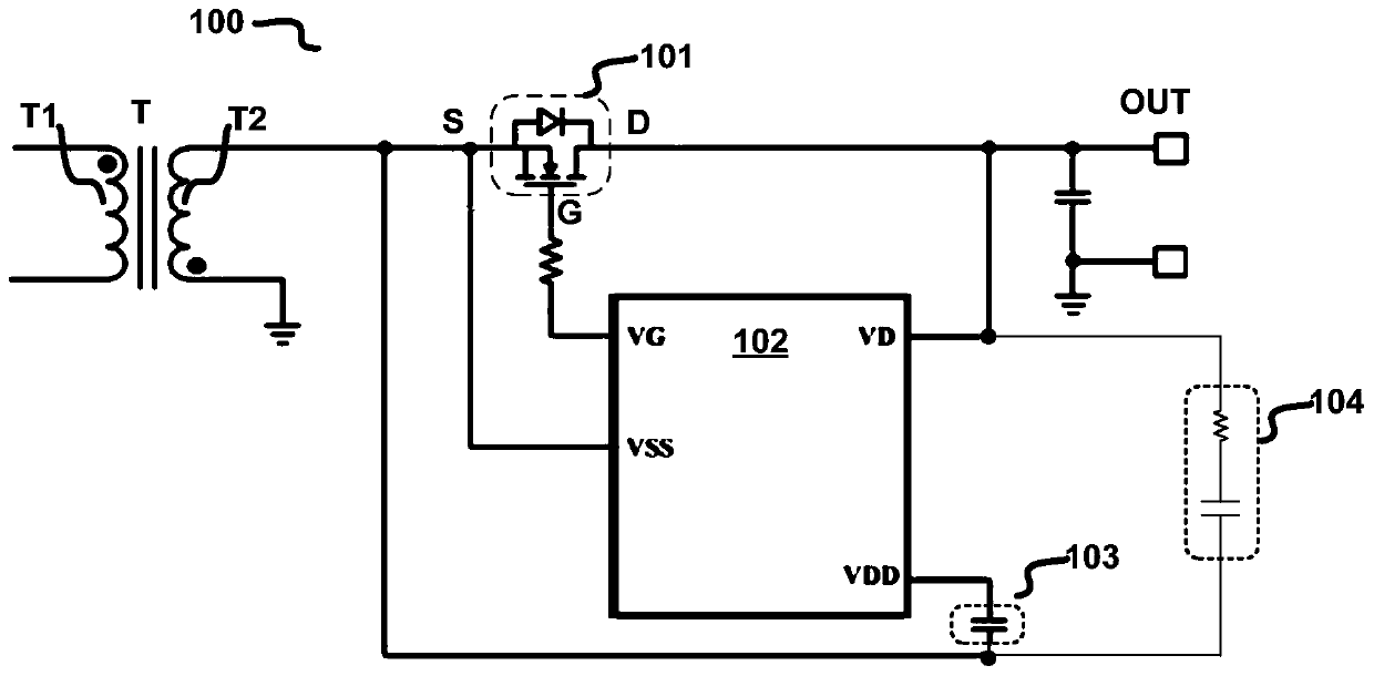
[0029] figure 1 A schematic circuit structure diagram of a synchronous rectification circuit 100 ...


PUM


Abstract

The embodiment of the invention discloses a driving circuit of a synchronous rectification device. The driving circuit comprises a controllable charging circuit and a slope detection circuit. The slope detection circuit is used for sensing whether the potential difference of a detection end of the driving circuit relative to a reference ground end of the driving circuit rises suddenly or not, andproviding a slope detection signal in response to the rising abrupt change edge of the potential difference so as to make the controllable charging circuit form a current path from the detection end to a power supply end and provide a charging current for the power supply end when the rising abrupt change edge of the potential difference occurs. According to the embodiment of the invention, the driving circuit can make the controllable charging circuit convert overshoot voltage spike energy generated in the rising abrupt change of the potential difference into the power supply potential of thewhole driving circuit when the potential difference of the detection end relative to the reference ground end rises and changes suddenly each time, so that the voltage spike be suppressed, the voltage spike energy is reasonably absorbed, converted and utilized, and the overall efficiency of the system is improved.

Description

technical field [0001] Embodiments of the present disclosure relate to an electronic circuit, in particular to a driving circuit for a synchronous rectification device. Background technique [0002] Synchronous rectification devices can be used in various applications, such as secondary switching devices for isolated converters such as resonant converters and flyback converters. During the working process of the isolated converter, each time the switching device on the primary side is turned on, a current path is formed on the primary side, and the voltage at both ends of the synchronous rectification device will increase rapidly due to mutual inductance on the secondary side (for example, the synchronous rectification device is a MOSFET , the voltage across its drain-source increases). At this time, the voltage at both ends of the synchronous rectification device will have a large voltage spike, which may cause undesired consequences such as damage to circuit components. ...

Claims


Application Information

Patent Timeline
Patent Type & Authority Applications(China)
IPC IPC(8): H02M1/08
CPCH02M1/08H02M3/33592H02M3/01H02M1/0006H02M1/0009H02M1/32H02M1/344Y02B70/10H02M1/0012H02M1/0054H02M7/217H02M1/0029H02M1/0038
Inventor 叶家佑陈跃东李晖
Owner CHENGDU MONOLITHIC POWER SYST
Why Eureka
Try Eureka