Plastic injection mold

A technology for injection molds and plastics, applied in the separation of dispersed particles, chemical instruments and methods, separation methods, etc., can solve problems affecting the health of workers, single exhaust function, etc. Ensure the effect of ventilation and material resistance

Active Publication Date: 2020-03-06
NINGBO SHUANGLIN IND PROD MFG CO LTD
View PDF3 Cites 3 Cited by
  • Summary
  • Abstract
  • Description
  • Claims
  • Application Information

AI Technical Summary

Problems solved by technology

[0003] Existing injection molds are often designed with related exhaust structures to eliminate air holes on the surface of the finished mold after the injection mold is formed, and in turn reduce the probability of defects on the surface of the fi

Method used


Image

  • Plastic injection mold
  • Plastic injection mold
  • Plastic injection mold

Examples


Embodiment Construction

[0023] The technical solution of this patent will be further described in detail below in conjunction with specific embodiments.

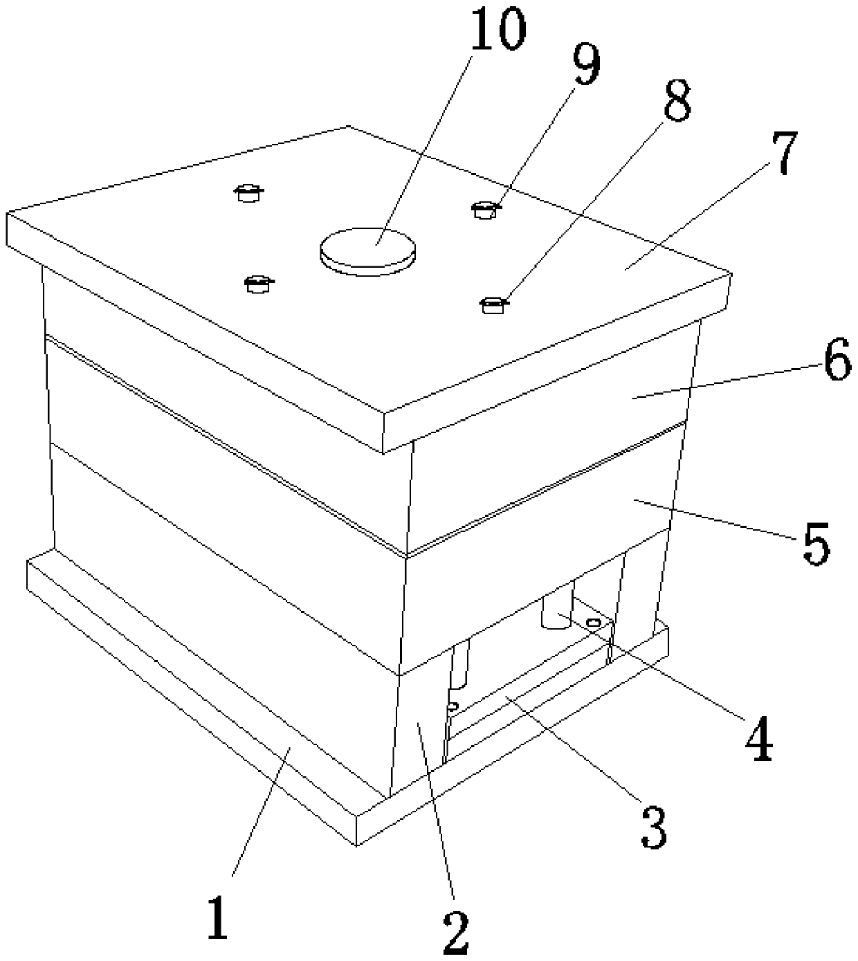
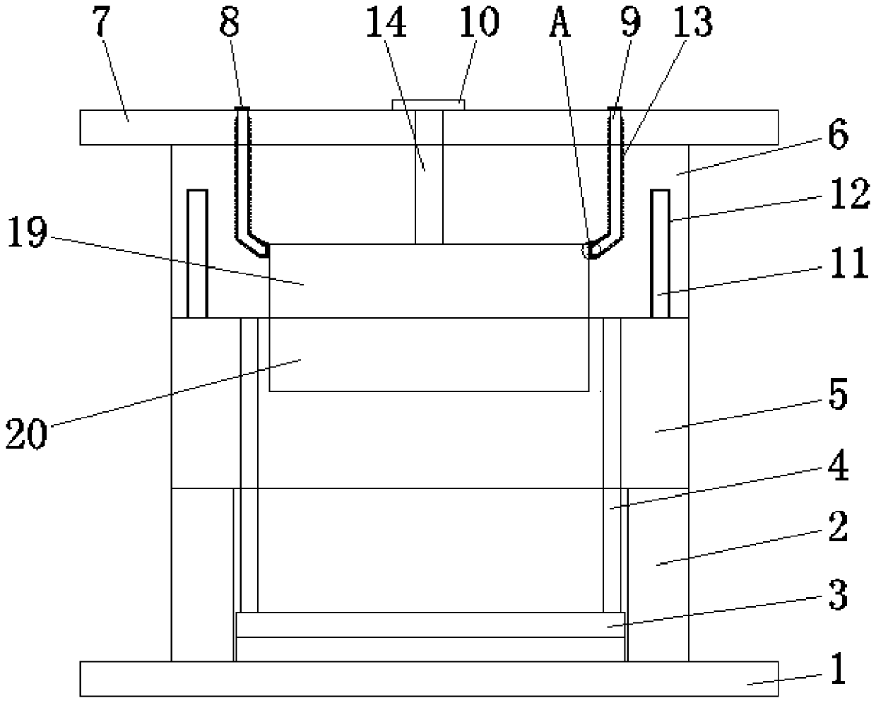
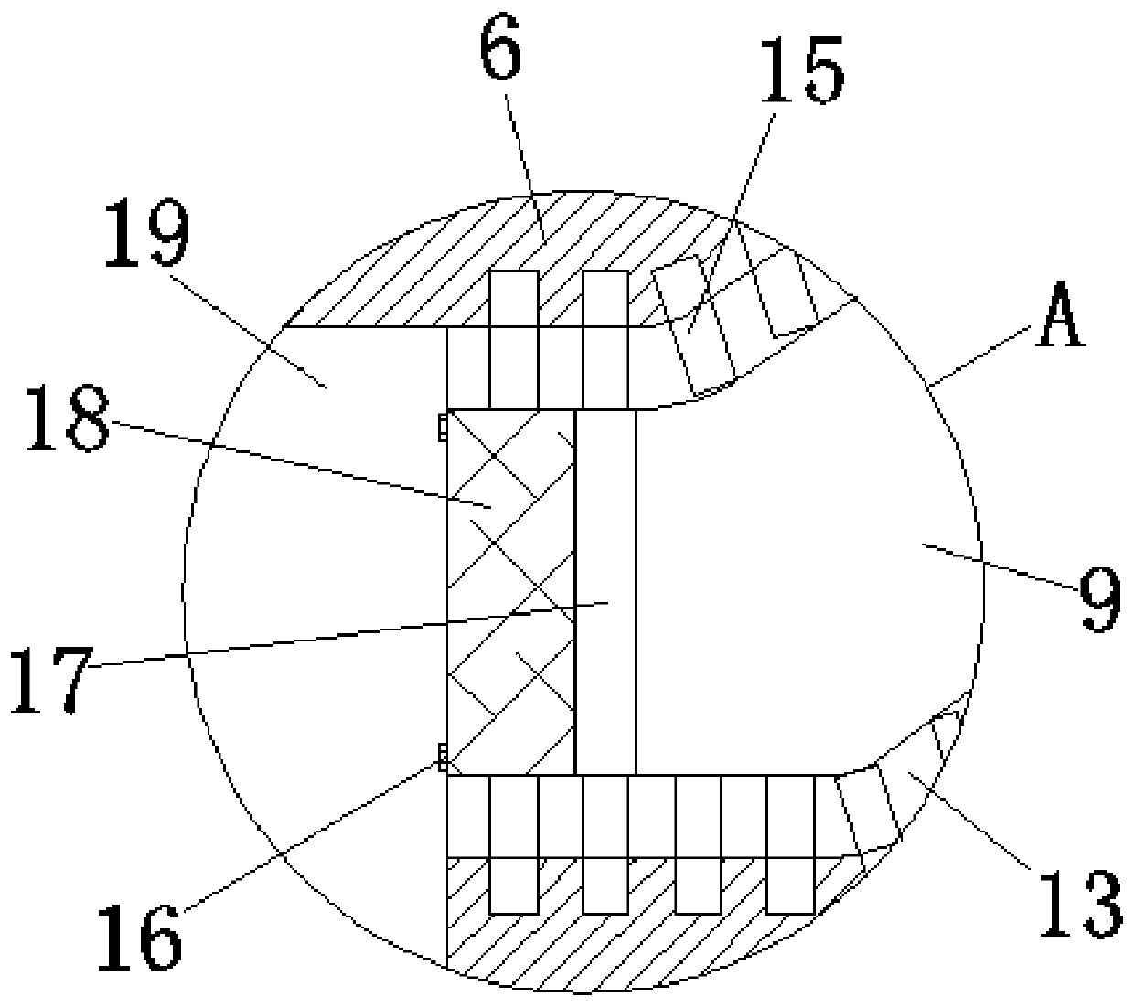
[0024] see Figure 1~5 , in an embodiment of the present invention, a plastic injection mold includes a rear formwork base plate 1, square irons 2 arranged symmetrically and in parallel are fixedly connected to both sides of the upper surface of the rear formwork base plate 1, and the two square irons 2 The bottom plate 1 of the rear formwork between them is fixedly connected with a thimble fixing plate 3, and the two sides of the upper surface of the thimble fixing plate 3 are fixedly connected with a plurality of symmetrically arranged thimble guide rods 4, and the top ends of the thimble guide rods 4 penetrate and slide into the rear mold In the holes on the corresponding surface of the frame 5, the positioning and docking of the rear mold frame 5 is realized, and the upper surface of the thimble fixing plate 3 is fixed with symmetrically arrang...


PUM


Abstract

The invention discloses a plastic injection mold, and relates to the technical field of injection molding. A rear formwork bottom plate is included. A rear formwork on the rear formwork bottom plate is detachably connected with a front formwork on a front formwork bottom plate. A cavity for mold injection molding is formed by a rear mold core formed by the upper portion of the rear formwork and afront mold core formed at the lower portion of the front formwork. Each exhaust assembly comprises a pipe cavity, wherein one end of the pipe cavity communicates with the cavity, the other end of thepipe cavity upwards extends out of the top face of the front formwork bottom plate, meanwhile, the pipe cavity is internally provided with a matched exhaust pipeline, and one end of the exhaust pipeline communicates with the cavity and is provided with a ventilation micro hole ring. According to the plastic injection mold, surplus air in the cavity is exhausted in time, accordingly, the phenomenonof air hole generation in the injection molding process is avoided, and the mold injection molding effect is improved; and an activated carbon adsorption plate can be utilized for adsorbing harmful molecules contained in hot melting plastic raw materials, and accordingly the body health of workers is facilitated while exhausting is guaranteed.

Description

technical field [0001] The invention relates to the technical field of injection molding, in particular to a plastic injection mold. Background technique [0002] The injection mold consists of a moving mold and a fixed mold. The moving mold is installed on the movable template of the injection molding machine, and the fixed mold is installed on the fixed template of the injection molding machine. During injection molding, the movable mold and the fixed mold are closed to form the gating system and the cavity, and the movable mold and the fixed mold are separated to take out the plastic product when the mold is opened. In order to reduce the heavy workload of mold design and manufacturing, most injection molds use standard molds. [0003] Existing injection molds are often designed with related exhaust structures to eliminate air holes on the surface of the finished mold after the injection mold is formed, and in turn reduce the probability of defects on the surface of the ...

Claims


Application Information

Patent Timeline
IPC IPC(8): B29C45/34B29C45/00B01D53/04
CPCB01D53/04B01D2253/102B29C45/0025B29C45/34
Inventor 刘大宇
Owner NINGBO SHUANGLIN IND PROD MFG CO LTD
Why Eureka
Try Eureka