

A thin plate quenching production line
A production line and thin plate technology, applied in the field of thin plate quenching production line, can solve problems such as saw blade quenching deformation, and achieve the effect of ensuring flatness, preventing workpiece deformation, and improving quenching efficiency
- Summary
- Abstract
- Description
- Claims
- Application Information
AI Technical Summary
Problems solved by technology
Method used
Image

Examples
Embodiment 1
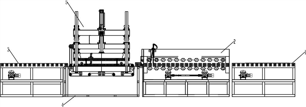
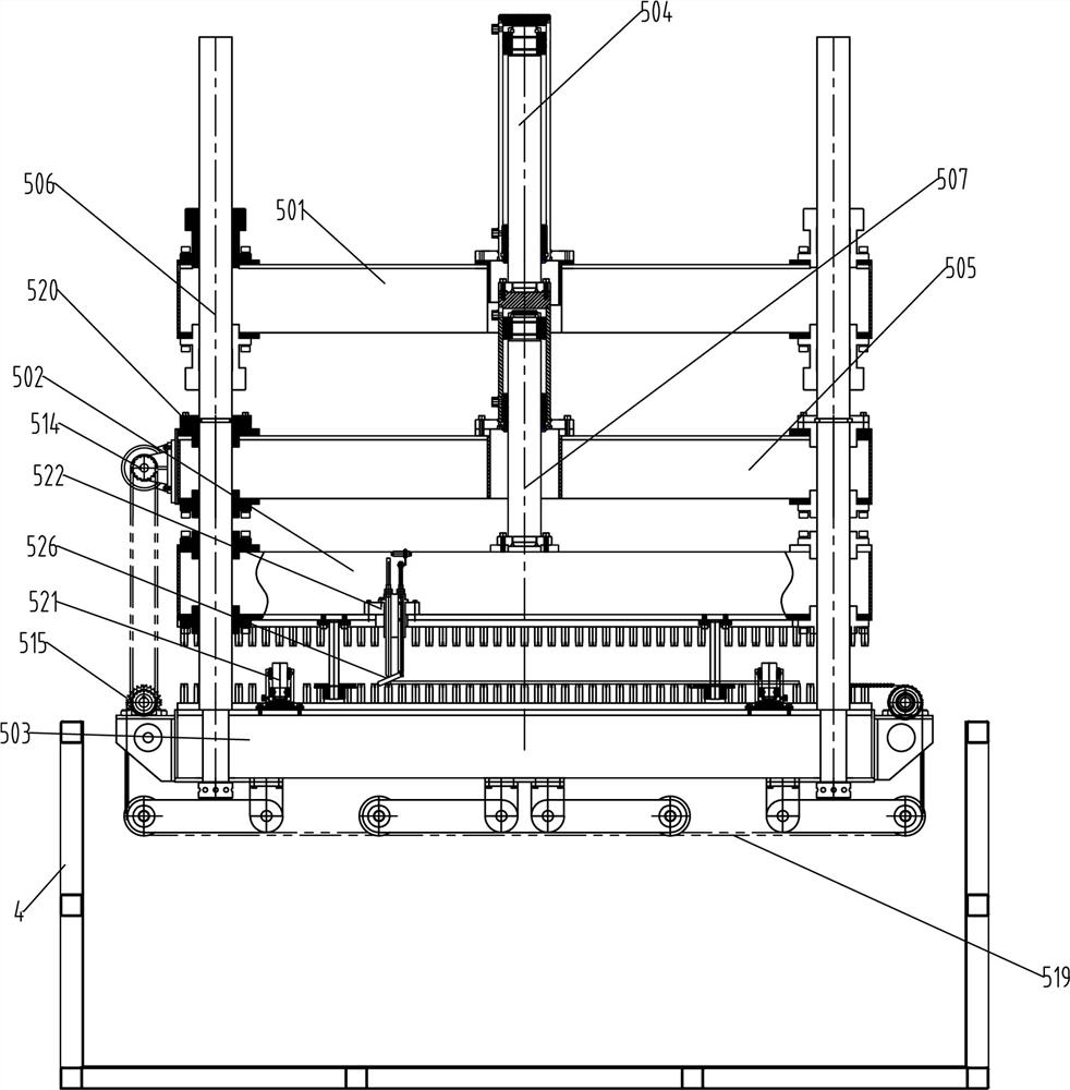
[0025] Embodiment 1: as Figure 1~2 As shown, a thin plate quenching production line includes a feed conveying mechanism 1, a roller hearth type continuous heating furnace 2, a quenching cooling device and a discharge conveying mechanism 3 arranged in sequence, and the feed conveying mechanism 1 and the discharge conveying mechanism 3 can be The roller conveyor is selected, and the roller hearth type continuous heating furnace 2 includes a furnace body and a conveying mechanism and heating elements arranged in the furnace body. The quenching and cooling device includes a quenching tank 4 and a press 5 arranged in the quenching tank 4. The press 5 A press conveying mechanism is arranged in the middle, and the press conveying mechanism is arranged between the outlet of the roller hearth type continuous heating furnace 2 and the discharge conveying mechanism 3 .
[0026] The descending mechanism 504 and the pressing mechanism 507 are hydraulic cylinders, and the hydraulic cylinde...
Embodiment 2
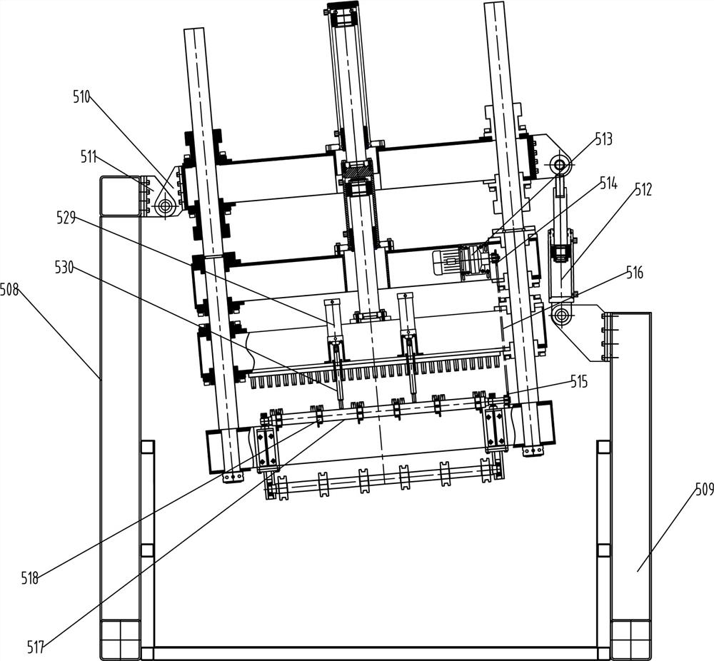
[0036] Embodiment 2: as different from Embodiment 1 image 3 As shown, the front and rear sides of the upper fixing seat 501 are provided with a first hinged ear plate 510, the upper ends of the first column 508 and the second column 509 are provided with a second hinged ear plate 511, and the second hinged ear plate 511 on the first column 508 is provided. The hinged lug 511 is hinged to the first hinged lug 510 on one side, the first hinged lug 510 on the other side is hinged to the upper end of the tilting telescopic mechanism 512, and the lower end of the tilting telescopic mechanism 512 is hinged to the second column 509. The two hinged lugs 511 are hinged. The tilt telescopic mechanism 512 is configured as a hydraulic cylinder.
[0037] The upper fixed seat 501 can be tilted by setting the tilting telescopic mechanism 512. When the workpiece is quenched, the tilting telescopic mechanism 512 is activated to tilt the side fixing seat 501, so that the workpiece can be imme...
Embodiment 3
[0038] Embodiment 3: as different from embodiment 1 and embodiment 2 Figure 4 As shown, the upper platen 502 is provided with a signal device, the signal device includes a mounting seat 522 installed on the upper platen 502, and the mounting seat 522 is provided with a through hole for the positioning rod 523 and the signal rod 524 to pass through. The positioning rod 523 and the signal rod 524 are provided with a limit nut 525, the lower end of the positioning rod 523 is hinged to the positioning block 526, the upper end is connected to the signal switch 527, the positioning block 526 is inclined to the signal rod 524 side, and the signal switch 527 is used to control the down mechanism 504 And the start of pressing mechanism 507, can also control the start of tilt telescopic mechanism 512 simultaneously.
[0039] A limiting block 528 is arranged on the lower end side of the positioning rod 523 , and the upper side of the positioning block 526 is in contact with the limiting...
PUM
 Abstract
Description
Claims
Application Information