
Electronic water pump and casing assembly

An electronic water pump and component technology, which is applied to pump components, pumps, and parts of pumping devices for elastic fluids, etc., can solve the problem of not meeting the strength requirements of the motor housing, the long injection molding time, and the volume of the stator injection layer. large problems, to achieve the effect of saving material costs, improving noise, and shortening injection molding time

Pending Publication Date: 2020-03-10
GUANGDONG WELLING AUTO PARTS CO LTD
View PDF0 Cites 4 Cited by
  • Summary
  • Abstract
  • Description
  • Claims
  • Application Information

AI Technical Summary

Problems solved by technology

The stator of the traditional electronic water pump is installed in the casing, the rotor and the impeller are in the hydraulic department, and there is an isolation sleeve between the stator and the rotor, which acts as a seal. The traditional electronic water pump has many parts, complex assembly, and high cost
[0003] A motor structure of an electronic water pump is disclosed in the related art. The stator assembly includes a mandrel, an armature, a rear thrust pad, and a stator injection molding layer. The armature, mandrel, and rear thrust pad are injection molded into one body. The role of the machine shell, end cover and stator spacer sleeve, the injection molding layer of the stator is a BMC thermosetting molding block, which has the following disadvantages: 1) The stator injection molding layer is made of a BMC thermosetting molding block, which has low strength and cannot meet the strength of the motor casing Requirements; 2) The volume of the injection molding layer of the stator is large, and the injection molding time is long, which is easy to cause damage to the windings wrapped inside the injection molding layer of the stator; 3) If the injection molding layer of the stator is made of PPS material with high strength, it will cause manufacturing costs Increase

Method used


Image

  • Electronic water pump and casing assembly
  • Electronic water pump and casing assembly
  • Electronic water pump and casing assembly

Examples


Embodiment Construction

[0036] In order to understand the above-mentioned purpose, features and advantages of the present invention more clearly, the present invention will be further described in detail below in conjunction with the accompanying drawings and specific embodiments. It should be noted that, in the case of no conflict, the embodiments of the present application and the features in the embodiments can be combined with each other.

[0037] In the following description, many specific details are set forth in order to fully understand the present invention. However, the present invention can also be implemented in other ways different from those described here. Therefore, the protection scope of the present invention is not limited by the specific details disclosed below. EXAMPLE LIMITATIONS.

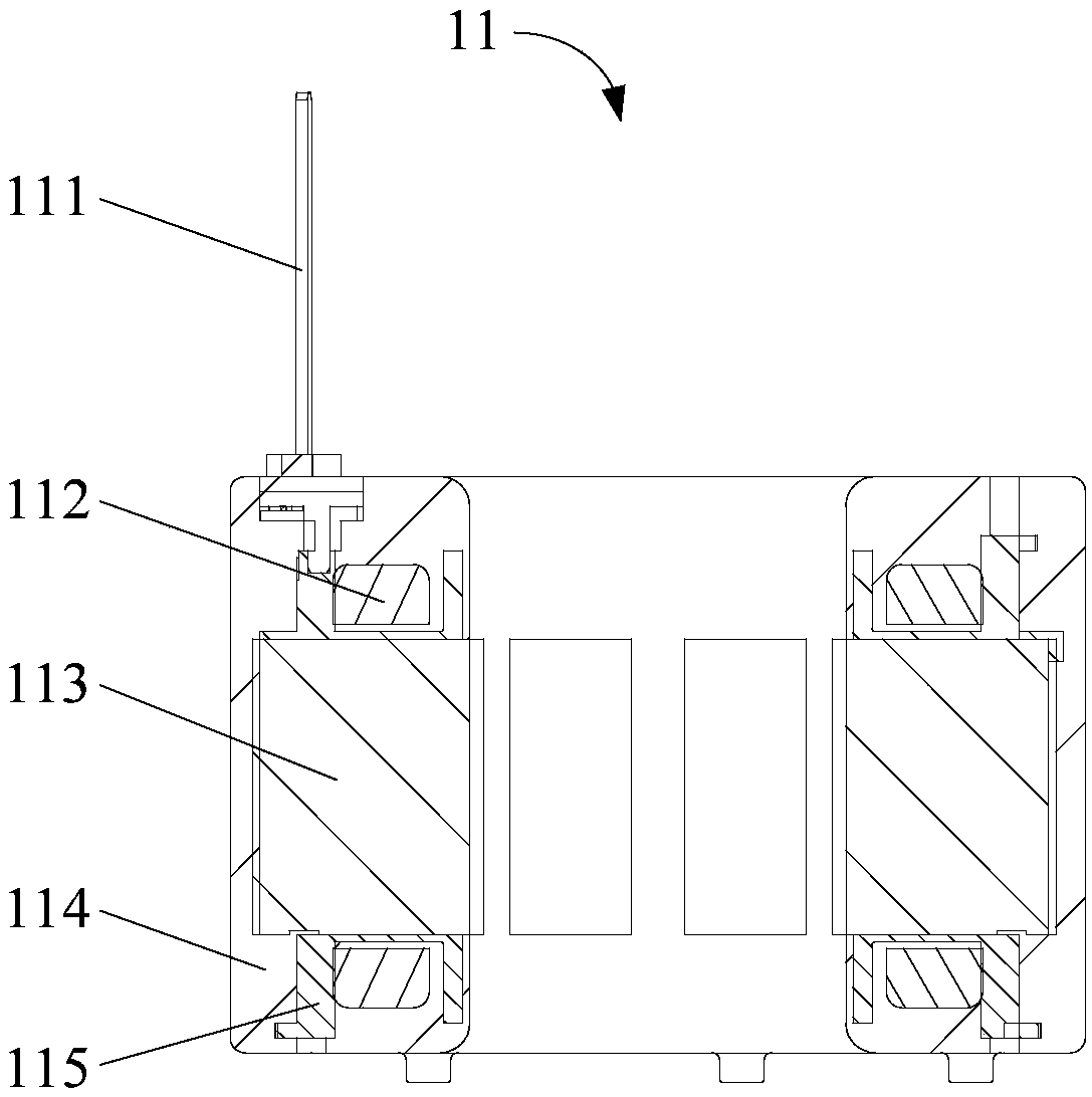
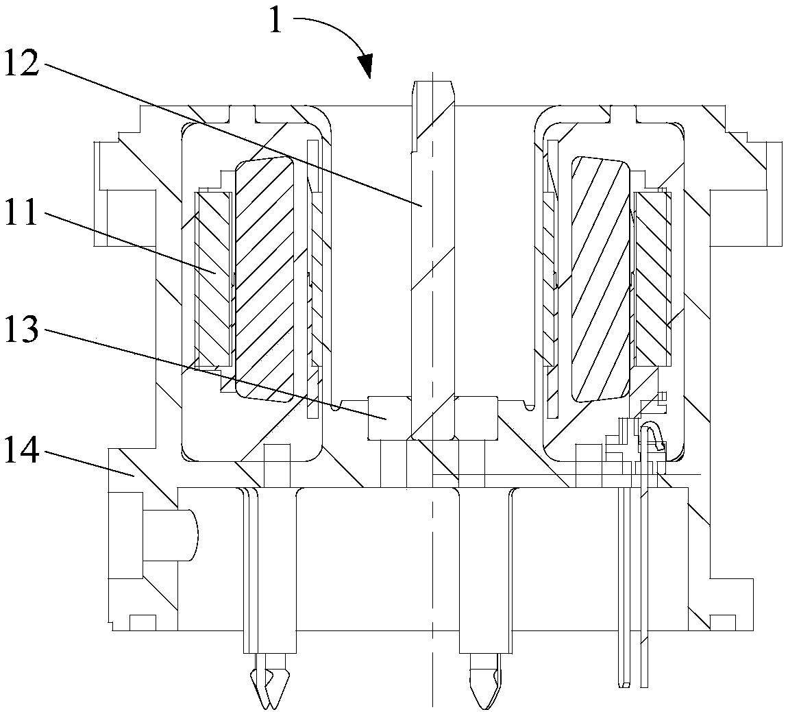
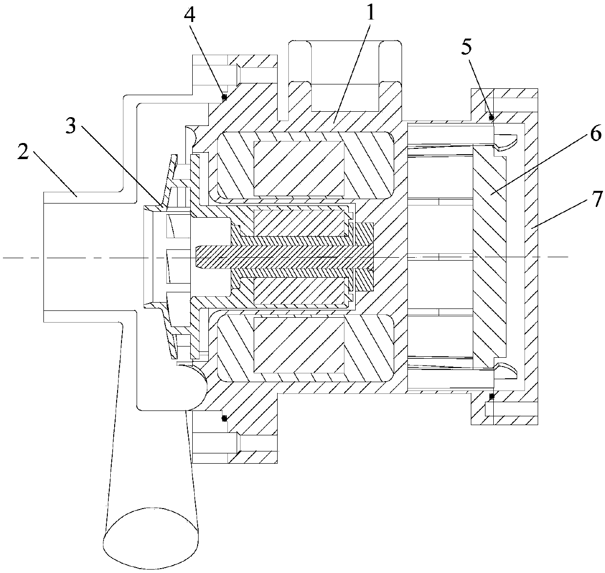
[0038] Refer below Figure 1 to Figure 4 The electronic water pump and its casing assembly according to some embodiments of the present invention are described.

[0039] Such as figure 2 and im...


PUM


Abstract

The invention provides an electronic water pump and a casing assembly. The casing assembly of the electronic water pump comprises a stator assembly, a rotating shaft, a shaft base and a casing injection body, wherein the stator assembly is formed by overall injection molding, the casing assembly is formed by secondary injection molding, the rotating shaft and the shaft base are both embedded intothe casing injection body, and the stator assembly is wrapped in the casing injection body to form self-sealing. According to the casing assembly of the electronic water pump, the stator assembly is formed by overall injection molding and then subjected to secondary injection molding with the casing and realizes the self-sealing action with a rotor, a distance sleeve in the middle of an air gap ofthe stator and the rotor is omitted, cost of a casing material is reduced, meanwhile, the assembling process of the electronic water pump is simplified, rigidity of the stator assembly is improved, noise improvement of the electronic water pump is facilitated, operating reliability of the electronic water pump is improved, and therefore, the casing assembly of the electronic water pump in the scheme has obvious advantages in aspects of mounting process, cost and properties.

Description

technical field [0001] The present invention relates to the technical field of electronic water pumps, in particular to a casing assembly of an electronic water pump and an electronic water pump including the casing assembly. Background technique [0002] In view of the environment of energy frugality, most modern high-end cars and electric vehicles replace the original mechanical water pumps with electronic cooling water pumps. Compared with traditional water pumps, electronic water pumps have the advantages of precise control and higher efficiency. The stator of the traditional electronic water pump is installed in the casing, the rotor and the impeller are in the hydraulic department, and there is a spacer sleeve between the stator and the rotor, which acts as a seal. The traditional electronic water pump has many parts, complex assembly, and high cost. [0003] A motor structure of an electronic water pump is disclosed in the related art. The stator assembly includes a m...

Claims


Application Information

Patent Timeline
IPC IPC(8): F04D13/06F04D29/40
CPCF04D13/0606F04D29/406
Inventor 王东葛笑陈华江
Owner GUANGDONG WELLING AUTO PARTS CO LTD
Learn More