Shift roller arrangement and transmission arrangement

A transmission and stopper technology, applied in transmission control, elements with teeth, belts/chains/gears, etc., to solve problems such as limited rotatability of shift rollers

Active Publication Date: 2020-03-10
MAGNA PT B V & CO KG
View PDF14 Cites 0 Cited by
  • Summary
  • Abstract
  • Description
  • Claims
  • Application Information

AI Technical Summary

Problems solved by technology

Here, however, the rotatability of the shifting roller is limited

Method used


Image

  • Shift roller arrangement and transmission arrangement
  • Shift roller arrangement and transmission arrangement
  • Shift roller arrangement and transmission arrangement

Examples


Embodiment Construction

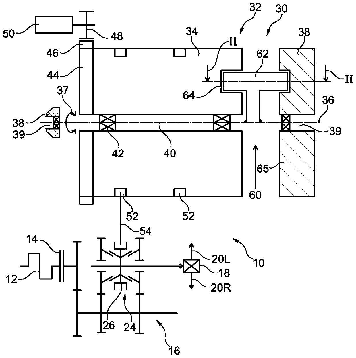
[0065] exist figure 1 A power train for a motor vehicle is schematically shown in and generally indicated at 10 . The drive train 10 has a drive motor 12 which can be formed by an internal combustion engine or by a hybrid drive unit.

[0066] Furthermore, the drive train 10 generally includes a clutch arrangement, which can be realized as a single clutch or as a double clutch. On the input side, a clutch device 14 is connected to the drive motor 12 . On the output side, the clutch device 14 is connected to a transmission device 16 for setting up a plurality of gears, wherein figure 1 The transmission arrangement 16 in is shown schematically as a stepped transmission in the form of a countershaft. The output of the transmission device 16 is connected to a differential 18 , by means of which the drive power can be distributed to the drive wheels 20L, 20R.

[0067] The transmission device 16 has a plurality of shifting clutches in order to set up different gears, wherein a sh...


PUM


Abstract

The invention relates to a shift roller arrangement (32) for a shift device (30) of a transmission arrangement (16), in particular for a motor vehicle, the shift roller arrangement comprising: a shiftroller body (34) which can be rotated about a shift roller shaft (40); and a stop device (60) for referring to the rotational position of the shift roller body (34), wherein the stop device (60) hasa stop element (62) which is designed in such a way that the stop element can be brought into contact with a housing stop (65) in a first reference position, and the stop element (62) is mounted so asto be rotatable relative to the shift roller body (34) in a rotationally limited manner in the rotational direction.

Description

technical field [0001] The invention relates to a shifting roller arrangement for a shifting system, in particular for a transmission arrangement of a motor vehicle, the shifting roller arrangement having a shifting roller body which is rotatable about a shifting roller axis , and has stop means for reference to the rotational position of the shift roller body. [0002] Furthermore, the invention relates to a transmission arrangement for a motor vehicle having a housing, a shifting device for shifting gears, wherein the shifting device has a shifting roller arrangement of the type described. Background technique [0003] Shifting devices for transmission arrangements are generally known in the prior art. [0004] Document DE 196 55 083 B4 discloses a shifting device of a transmission having shift rollers integrated into the transmission housing. The clutch actuating actuator is formed separately therefrom. [0005] Furthermore, WO 97 / 02963 A discloses a shifting device fo...

Claims


Application Information

Patent Timeline
Patent Type & Authority Applications(China)
IPC IPC(8): F16H63/16F16H63/42
CPCF16H63/16F16H63/42F16H61/32F16H63/18F16H2061/283F16H2342/02
Inventor 斯特凡·卡普格奥尔格·布加特
Owner MAGNA PT B V & CO KG
Why Eureka
Try Eureka