
Integrated driving module with energy conversion function and manufacturing method thereof

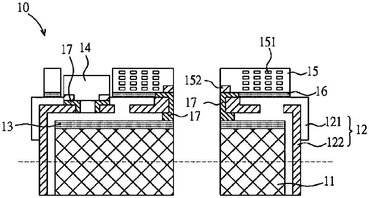
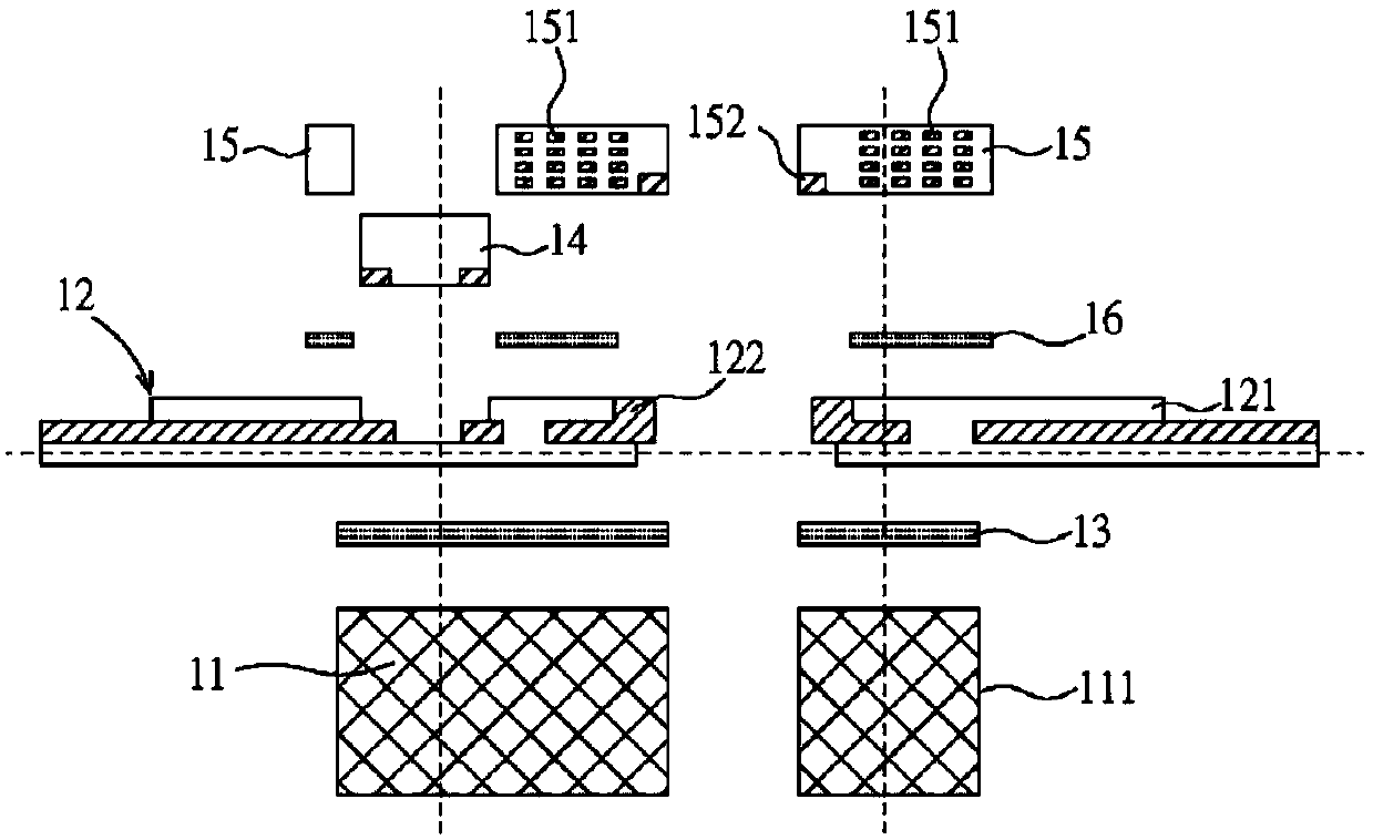
A driving module and energy conversion technology, applied in color TV parts, TV system parts, TV and other directions, can solve the problem of size, thickness limitation, cannot be effectively reduced, affect yield and other problems, and reduce the overall size and thickness, reduce the manual assembly process, and improve the effect of product accuracy

Active Publication Date: 2020-03-10
PHOENIX PIONEER TECH
View PDF6 Cites 0 Cited by
  • Summary
  • Abstract
  • Description
  • Claims
  • Application Information

AI Technical Summary

Problems solved by technology

The magnetic drive device thus obtained has at least the following disadvantages: (1) These components are produced by different manufacturers, which means that the size and thickness of each component will be limited and cannot be effectively reduced, resulting in an overall thickness of 800 Micron; (2) The number of components is large and must be assembled manually, so the product accuracy is insufficient and will affect the yield; (3) Inheriting the previous two points, it will make it difficult to reduce the cost

Method used


Image

  • Integrated driving module with energy conversion function and manufacturing method thereof
  • Integrated driving module with energy conversion function and manufacturing method thereof
  • Integrated driving module with energy conversion function and manufacturing method thereof

Examples


Embodiment Construction

[0070] The technical solutions in the embodiments of the present invention will be clearly and completely described below with reference to the accompanying drawings in the embodiments of the present invention. Many specific details are set forth in the following description to facilitate a full understanding of the present invention, but the present invention can also be implemented in other ways different from those described herein, and those skilled in the art can do so without departing from the connotation of the present invention. Similar promotion, therefore, the present invention is not limited by the specific embodiments disclosed below.

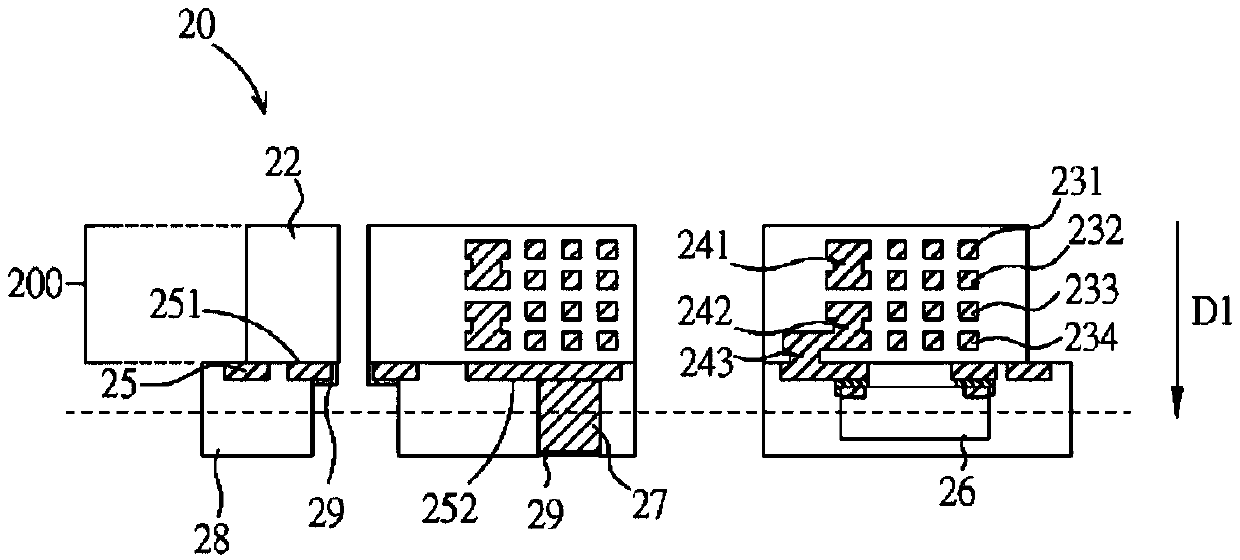
[0071] Please refer to figure 2 As shown, an integrated driving module 20 with energy conversion function according to a preferred embodiment of the present invention includes a patterned conductive circuit layer 25 , an integrated electromagnetic induction component layer 200 , and a second dielectric layer 28 , an embedded comp...


PUM


Abstract

An integrated driving module with an energy conversion function comprises a patterned conductive circuit layer, an integrated electromagnetic induction assembly layer, a second dielectric layer, an embedded assembly and a conductive assembly. The integrated electromagnetic induction assembly layer is arranged on the patterned conductive circuit layer and comprises a plurality of conductive coil layers, a plurality of conductive connecting assemblies and a first dielectric layer. The conductive coil layers are arranged in a stacked mode, and the conductive connecting assemblies are electricallyconnected between the conductive coil layers and between the corresponding conductive coil layers and the patterned conductive circuit layer respectively. The first dielectric layer wraps the conductive coil layers and the conductive connection assemblies. The second dielectric layer is formed on the patterned conductive circuit layer and wraps the patterned conductive circuit layer. The embeddedcomponent and the conductive component are both arranged in the second dielectric layer, and the embedded component is electrically connected with the patterned conductive circuit layer. One end of the conductive component is electrically connected with the patterned conductive circuit layer, and the other end surface is exposed to the second dielectric layer.

Description

technical field [0001] The present invention relates to a driving module and a manufacturing method thereof, and in particular, to an integrated driving module with an energy conversion function and a manufacturing method thereof. Background technique [0002] With the prevalence of social networking sites and the increasingly powerful camera functions of smart phones, people rely more and more on the cameras of smart phones to take pictures and videos, and more and more technologies originally used in traditional cameras and video recorders are introduced into mobile phone cameras among. In order to overcome the problem of hand-shake and blur in mobile phone night shooting and photography, the built-in anti-shake function of mid-to-high-end mobile phones is becoming more and more common. [0003] One of the anti-shake technologies is Optical Image Stabilization (OIS). It can be used for anti-shake in photography and photography. The advantage of optical anti-shake is hig...

Claims


Application Information

Patent Timeline
IPC IPC(8): H04N5/232H04N5/225
CPCH04N23/54H04N23/685
Inventor 胡文宏陈宗岳
Owner PHOENIX PIONEER TECH
Learn More