Bridge-shaped contact riveting clamp of frame circuit breaker and assembly operation method of bridge-shaped contact riveting clamp

A frame circuit breaker and bridge contact technology, which is applied to circuits, feeding devices, positioning devices, etc., can solve the problems of slow riveting speed, inability to meet production progress, and scrapped workpieces, and achieve good force and fast riveting speed. , the effect of high efficiency

Pending Publication Date: 2020-03-13
杭州杰涵机械科技有限公司
View PDF0 Cites 0 Cited by
  • Summary
  • Abstract
  • Description
  • Claims
  • Application Information

AI Technical Summary

Problems solved by technology

The bridge contact riveting method of the traditional frame circuit breaker is to use the conical surface to resist the end hole of the bridge contact pin, and manually hammer the pin to expand to achieve the purpose of riveting. This method is often difficult due to uneven artificial force. The contact of the bridg

Method used


Image

  • Bridge-shaped contact riveting clamp of frame circuit breaker and assembly operation method of bridge-shaped contact riveting clamp
  • Bridge-shaped contact riveting clamp of frame circuit breaker and assembly operation method of bridge-shaped contact riveting clamp
  • Bridge-shaped contact riveting clamp of frame circuit breaker and assembly operation method of bridge-shaped contact riveting clamp

Examples


Example Embodiment

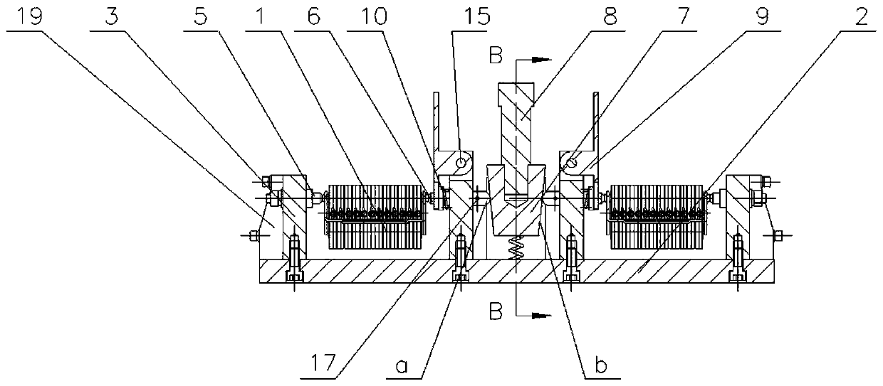
[0029] Embodiment 1: As shown in the figure, a bridge contact riveting fixture for a frame circuit breaker includes a bridge contact 1 and a bottom plate 2. The upper part of the bottom plate 2 is provided with two spaced clamps Device, the clamping device is provided with a detachable fixed bridge contact 1, and a punch riveting device is arranged between the two clamping devices, and the punch riveting device synchronously controls the two clamping devices.
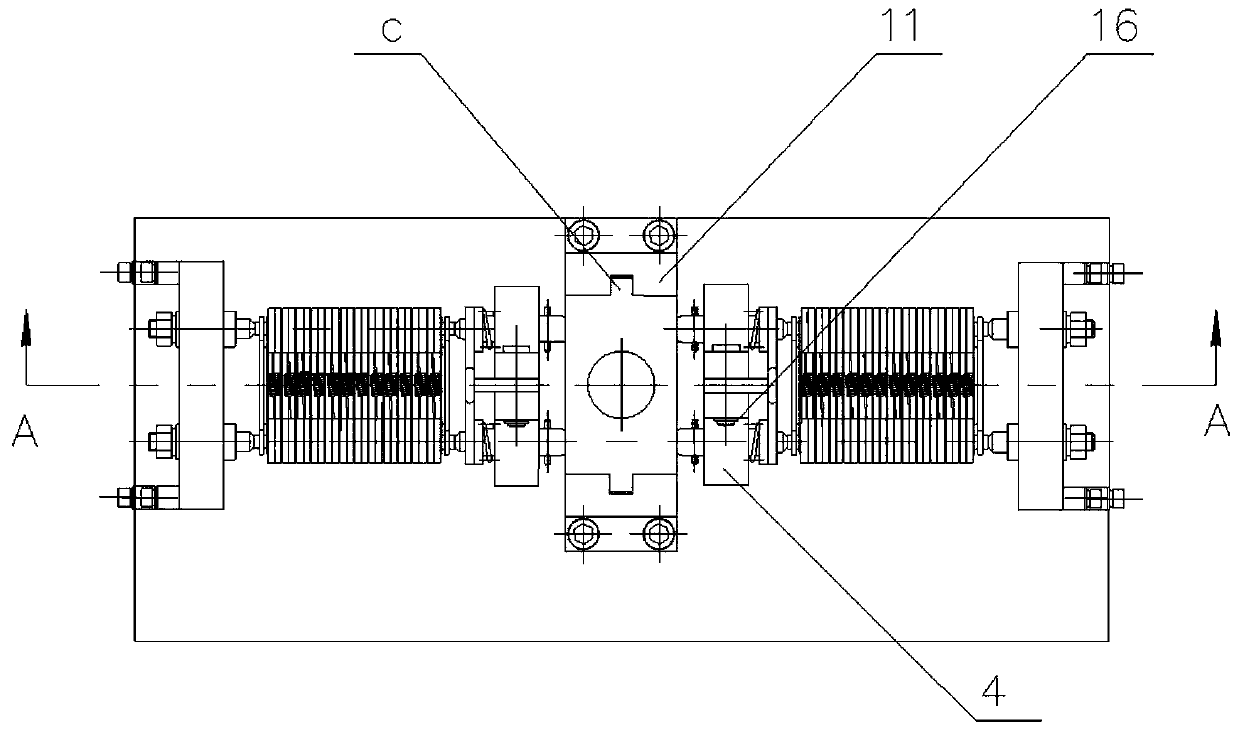
[0030] Preferably, the clamping device includes a support 3 and a support 4 arranged on the bottom plate 1. The support 3 and the support 4 are spaced apart, and the support 4 is provided with a fixed center 5 , The supporting base 4 is provided with a movable center 6, and the bridge-shaped contact 1 is arranged between the fixed center 5 and the movable center 6;

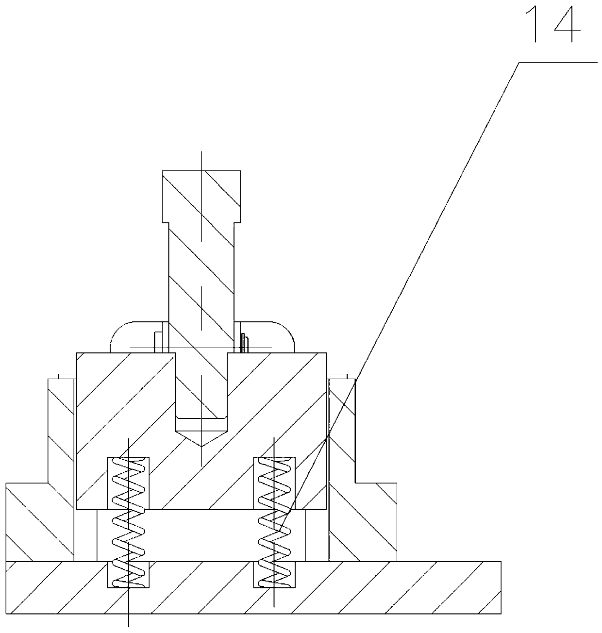
[0031] The punch riveting device includes a movable block 7, the movable block 7 is displaced downward by a punch 8, and the punch 8 drives the movable center 6...


PUM


Abstract

The invention relates to a riveting clamp, and in particular to an assembly operation method of a bridge-shaped contact riveting clamp of a frame circuit breaker. The riveting clamp comprises bridge-shaped contacts and a bottom plate; two clamping devices which are distributed at an interval are arranged on the bottom plate; the bridge-shaped contacts which are detachably fixed are respectively arranged in the clamping devices; a punch riveting device is arranged between the two clamping devices; and the punch riveting device synchronously controls the two clamping devices. The high riveting speed is fast, and efficiency is high.

Description

technical field [0001] The invention relates to a riveting fixture, in particular to an assembly operation method for a bridge-shaped contact riveting fixture of a frame circuit breaker. Background technique [0002] The main function of the bridge contact of the frame circuit breaker is to quickly connect or separate the circuit breaker body and the conductor of the drawer seat. It is suitable for quickly pulling out from the drawer seat when the body fails, and is convenient for maintenance. The commonly used bridge-shaped contact structure mainly includes: spacers, springs, small shafts, contacts, brackets, and pins. The two ends of the spring are respectively hooked on the small shafts in the semicircular arcs outside the contacts on both sides. There is a groove in the middle of the small shaft so that the hooks at both ends of the spring can be hooked. The bridge contact riveting method of the traditional frame circuit breaker is to use the conical surface to resist t...

Claims


Application Information

Patent Timeline
IPC IPC(8): B21D39/00B21D43/00H01H11/04
CPCB21D39/00B21D43/003H01H11/04
Inventor 陈佳成袁迪飞
Owner 杭州杰涵机械科技有限公司
Why Eureka
Try Eureka