

Terminal post riveting device and breaking tool
A riveter and pole technology, which is used in manufacturing tools, metal processing, metal processing equipment, etc., can solve problems such as poor, easy to loose electrical contacts, and achieve the effect of simplifying the structure, avoiding increased stress, and reducing working pressure.
Inactive Publication Date: 2011-06-15
MEISHAN HENGSHENG MECHANICAL EQUIP
View PDF5 Cites 0 Cited by
- Summary
- Abstract
- Description
- Claims
- Application Information
AI Technical Summary
Problems solved by technology
The pole rivet riveter and the cutting tool proposed by the present invention are to solve the problem that the existing pole bolt connection is easy to loose and cause poor electrical contact
At the same time, it also provides a cutting tool after riveting to solve the problem of convenient maintenance of pole rivets
Method used
View moreImage
Smart ImageViewing Examples

Examples
Embodiment 1
Embodiment 2
Login to View More PUM
 Abstract
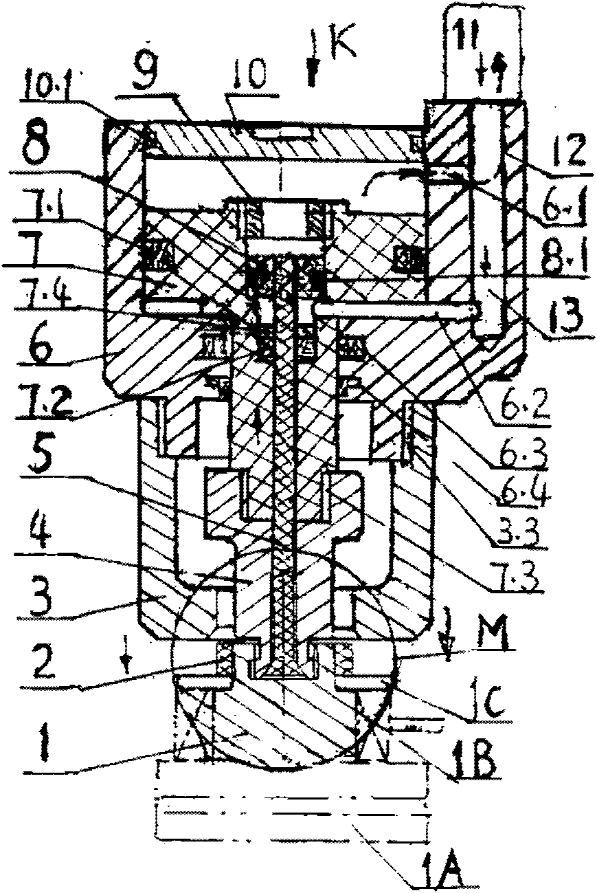
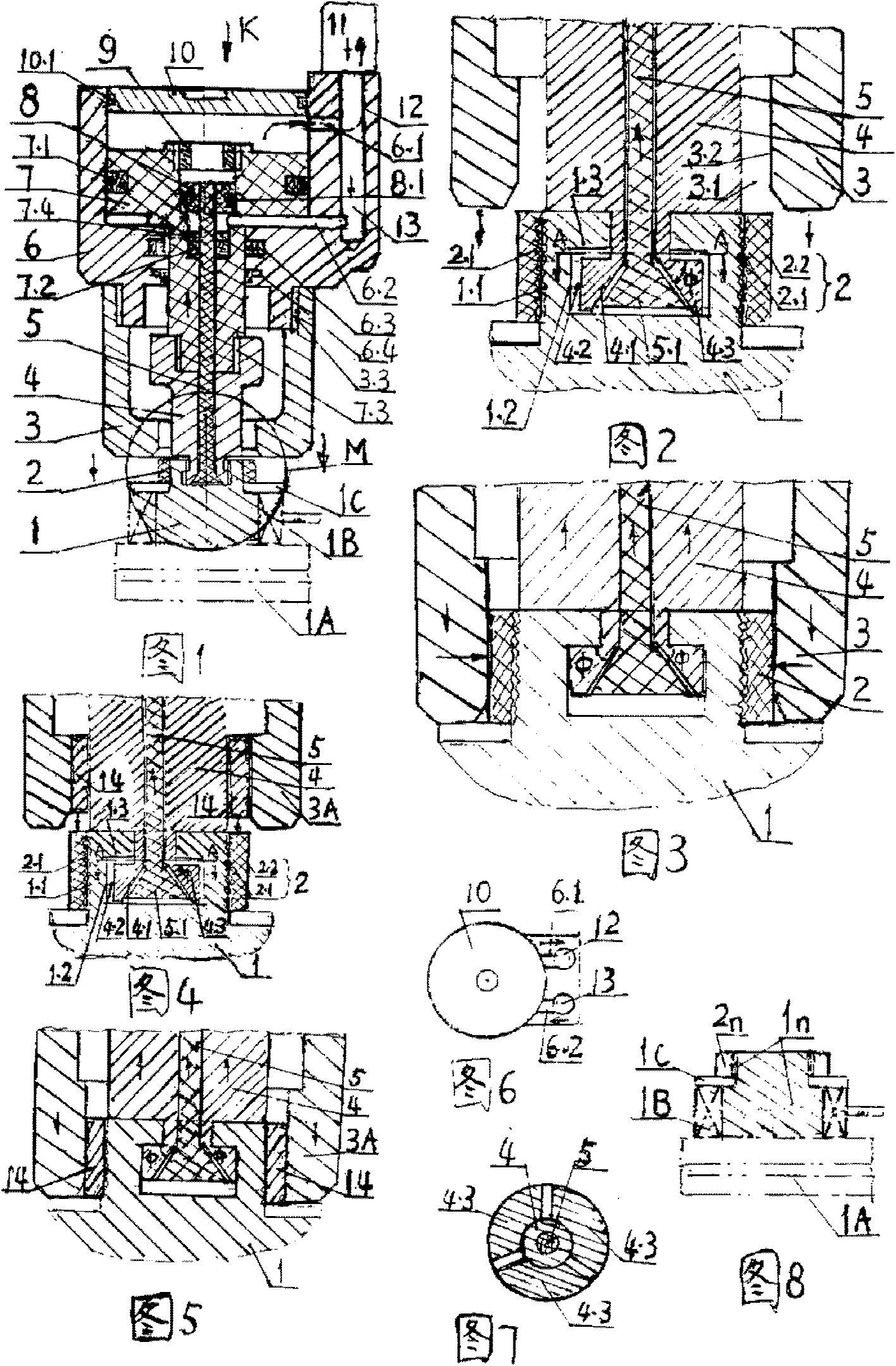
The invention relates to a terminal post riveting device and a breaking tool. A strut is arranged at the center of a cylinder body; a grabbing rod is tightly sheathed outside the strut; the bottom ends of the strut and the grabbing rod are inserted in a T-shaped groove formed on the upper plane of the terminal post of a battery; the strut has a horn-shaped bottom end; and the bottom end of the grabbing rod is a three-flap centripetal clamping body matched with the strut and the T-shaped groove. The oil cylinder consists of a cylinder body on the upper end, a jacket on the lower end, wherein the cylinder body is connected with the jacket through threads; a strut piston fixed with the upper end of the strut and a rivet piston at the periphery are arranged in the cylinder body; and the lower end of the rivet piston is connected with the grabbing rod through threads to form a single-oil-path double-piston structure. When the oil cylinder is started, the two pistons act to drive the strut and the grabbing rod to move upwards, and drive the jacket and the cylinder to move downwards so as to extrude the outer liner ring of the terminal post, thereby achieving the riveting. When a cutting head is mounted on the bottom end of the jacket, the pistons drive the cutting head to cut the liner ring as a breaking tool. By adopting cold riveting, the terminal post riveting device can solve the problem of bolt looseness of the terminal post. The invention also provides a riveting breaking tool, which facilitates the maintenance. The overall dimension of the terminal post riveting device is Phi40*100, the weight is about 1.5 kg, the cylinder pressure is about 12 Mpa; and the terminal post riveting device has high riveting speed and is convenient in operation.
Description
Pole rivet riveters and breaking tools (1) Technical field: pole rivet riveter and cutting tool, used for riveting and removal of pole rivets connected to battery electrodes of electric vehicles, is a cold-drawn rivet riveting and removal tool, belonging to the riveting category. (two) background technology: The electrode connection method of the existing electric vehicle storage battery adopts bolt connection, as shown in Figure 8, the diameter of the upper end of the electrode 1n on the storage battery 1A is smaller than that of the lower end, and the outer circle is a pole screw with external thread, and the nut 2n is installed on the pole screw. In addition, the two threads are engaged. When installing, firstly fit the conductive ring 1B of the electric lead on the outer circle of the lower end of the electrode 1n, spin the nut 2n, press the washer 1C under the nut tightly and then lock the conductive ring 1B to prevent the conductive ring from moving upward along the lo...
Claims
Login to View More Application Information
Patent Timeline
 Patent Type & AuthorityApplications(China)
IPC IPC(8): B23P19/04
Inventor张永明张森林
OwnerMEISHAN HENGSHENG MECHANICAL EQUIP