
High-temperature bonding device with clamping structure for accurate bonding

A technology of clamping structure and bonding device, applied in the field of high-temperature bonding device, can solve problems such as affecting the efficiency and quality of pipe bonding, poor stability of the clamping and clamping structure, and inability to fully consider clamping, etc. performance and cost-effectiveness, reducing the use of labor costs, and the effect of low cost

Inactive Publication Date: 2020-03-13
SUZHOU ZHIRUI PHOTOELECTRIC MATERIAL TECH CO LTD
View PDF0 Cites 1 Cited by
  • Summary
  • Abstract
  • Description
  • Claims
  • Application Information

AI Technical Summary

Problems solved by technology

[0004] The purpose of the present invention is to provide a high-temperature bonding device with a clamping structure for precise bonding, so as to solve the problem that the high-temperature bonding device on the market proposed in the above-mentioned background technology cannot fully clamp two sections of pipes for bonding processing. Consider the clamping of pipes of different sizes. Only one size of pipe can be clamped for processing. The practicability and cost performance are low. The stability of the clamping structure is poor, which affects the efficiency and efficiency of pipe bonding. quality problem

Method used


Image

  • High-temperature bonding device with clamping structure for accurate bonding
  • High-temperature bonding device with clamping structure for accurate bonding
  • High-temperature bonding device with clamping structure for accurate bonding

Examples


Embodiment Construction

[0021] The following will clearly and completely describe the technical solutions in the embodiments of the present invention with reference to the accompanying drawings in the embodiments of the present invention. Obviously, the described embodiments are only some, not all, embodiments of the present invention. Based on the embodiments of the present invention, all other embodiments obtained by persons of ordinary skill in the art without making creative efforts belong to the protection scope of the present invention.

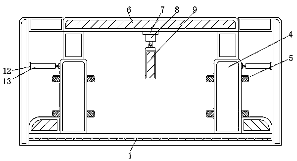
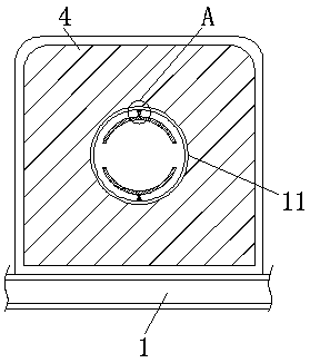
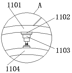
[0022] see Figure 1-5 , the present invention provides a technical solution: a high-temperature bonding device for precise bonding with a clamping structure, including a main body 1, a slide rail 2, a slider 3, a support column 4, a limit block 5, a fixing plate 6, a second A hydraulic rod 7, a first telescopic rod 8, a heating plate 9, a heating wire 10, an engaging assembly 11, a fixing ring 1101, a second hydraulic rod 1102, a second telescopic rod 1103, a...


PUM


Abstract

The invention discloses a high-temperature bonding device with a clamping structure for accurate bonding. The high-temperature bonding device comprises a main body and a fixing plate; sliding rail arearranged on the upper end in the main body; sliding block are respectively clamped in the sliding rails; supporting column are respectively welded and fixed at the upper ends of the sliding blocks; limiting blocks are welded and fixed at the right side of each supporting column; and the fixing plate is welded and fixed at the upper end of the main body. According to the high-temperature bonding device with the clamping structure for accurate bonding, second hydraulic rods are started; a second telescopic rod can move downwards with a fixing ring through a third hydraulic rod, and a clamping fixing ring arranged at the upper end is pushed downwards; and a second telescopic rod arranged at the bottom of the fixing ring moves the clamping fixing ring upwards through one second hydraulic rod,so that a pipeline needing to be bonded can be clamped and fixed. In addition, the structure can be suitable for clamping and fixing pipelines with different sizes, so that practicability and use cost performance of the high-temperature bonding device with the clamping structure are improved.

Description

technical field [0001] The invention relates to the technical field of high-temperature bonding devices, in particular to a high-temperature bonding device with a clamping structure for precise bonding. Background technique [0002] At present, the main pipeline mainly adopts hot-melt connection. Hot-melt connection is a kind of high-temperature bonding device. The principle of high-temperature bonding device is to put the mating surface of two PE pipes on the heating tool to heat the flat end surface until it melts. After walking the heating tool, the two molten end faces are pressed together and kept under pressure until the joint cools down to make it a whole. [0003] The high-temperature bonding device on the market cannot fully consider the clamping of pipes of different sizes when clamping two sections of pipes for bonding processing, and can only clamp pipes of one size for processing, which is relatively practical and cost-effective. Low, the stability of the clamp...

Claims


Application Information

Patent Timeline
Patent Type & Authority Applications(China)
IPC IPC(8): B29C65/02B29C65/22B29C65/78
CPCB29C65/02B29C65/22B29C65/7841B29C65/7858B29C66/522
Inventor 顾黎明
Owner SUZHOU ZHIRUI PHOTOELECTRIC MATERIAL TECH CO LTD
Learn More