Flanging machine for power distribution cabinet manufacturing and using method thereof

A technology for power distribution cabinets and folding machines, which is applied to manufacturing tools, metal processing equipment, feeding devices, etc., can solve the problems of inconvenient use, inconvenient adaptation to changing the angle of folding, and inconvenience to drive the displacement of raw materials, etc. Easy to set up, easy to use, easy to change the effect

Active Publication Date: 2020-03-17
广州市顺承电气设备有限公司
View PDF5 Cites 0 Cited by
  • Summary
  • Abstract
  • Description
  • Claims
  • Application Information

AI Technical Summary

Problems solved by technology

[0003] During the manufacturing process of the power distribution cabinet, the raw materials need to be folded. The existing folding machine for the production of the power distribution cabinet is inconvenient to drive the displacement of the raw material, resulting in the inconvenience of changing the length of the folded edge, and inconvenient to adapt to raw materials of different thicknesses. and change the angle of the hem, resulting in inconvenience

Method used


Image

  • Flanging machine for power distribution cabinet manufacturing and using method thereof
  • Flanging machine for power distribution cabinet manufacturing and using method thereof
  • Flanging machine for power distribution cabinet manufacturing and using method thereof

Examples


Embodiment 1

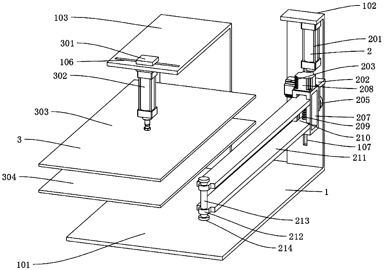
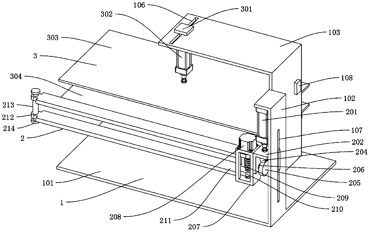
[0045] like Figure 1-Figure 7 As shown, the edge folding machine used for the manufacture of power distribution cabinets includes a support mechanism 1. The support mechanism 1 includes a bottom plate 101, a support plate 102, a support plate 2 103, a support plate 3 104, and a chute 105. The upper end of the bottom plate 101 is welded There is a support plate 102, and the support plate 102 is vertically formed with a chute 3 107, and one side of the support plate 102 is provided with a support plate 103, and the shape of the support plate 102 and the support plate 2 103 is "L" shape Support plate 1 102 and support plate 2 103 stably support the folding mechanism 2 and clamping mechanism 3, and the top of support plate 103 is horizontally formed with chute 2 106, which is used to facilitate the sliding of slider 301. The control switch 108 is installed at the rear end of the second board 103, the front end of the second board 103 is welded with the third board 104, the third ...

Embodiment 2

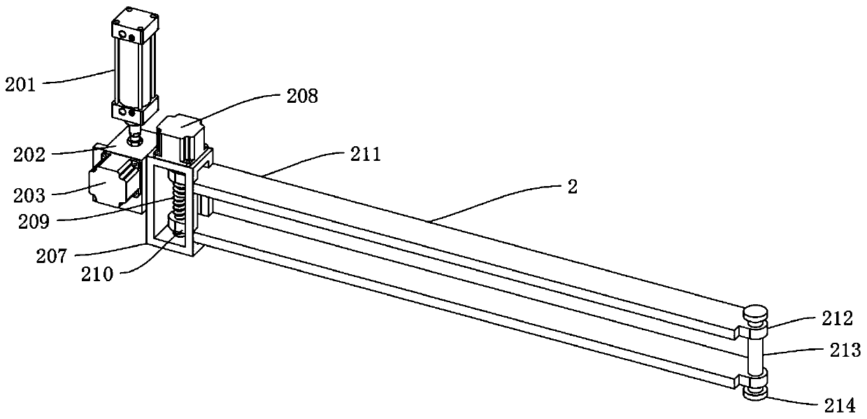
[0052] like Figure 8 As shown, the difference between Embodiment 2 and Embodiment 1 is that the clamping mechanism 3 includes a slide block 301, a cylinder two 302, an upper splint 303, a lower splint 304, and a push plate 309, and the lower end of the slide block 301 is equipped with a cylinder two 302, and the cylinder The lower end of the second 302 is provided with an upper splint 303, the lower end of the upper splint 303 is provided with a lower splint 304, the lower splint 304 is slidingly connected with the upper end of the support plate 3 104, and the lower end of the lower splint 304 is welded with a push plate 309 near the rear side. The inner side of one 105 is slidingly connected with support plate three 104, and one side of push plate 309 is horizontally connected with cylinder three 308 by bolts, and the push plate 309 is fastened with cylinder three 308, and cylinder three 308 is connected with support plate three 104 by bolts, and the cylinder One 201, one mo...


PUM


Abstract

The invention discloses a flanging machine for power distribution cabinet manufacturing and a using method thereof. The flanging machine comprises a supporting mechanism, wherein the supporting mechanism comprises a bottom plate, a first supporting plate, a second supporting plate, a third supporting plate and a first sliding groove, the first supporting plate is welded to the upper end of the bottom plate, a third sliding groove is vertically formed in the first supporting plate, the second supporting plate is arranged on one side of the first supporting plate, a second sliding groove is horizontally formed in the top of the second supporting plate, a control switch is installed at the rear end of the second supporting plate, the third supporting plate is welded to the front end of the second supporting plate, the first sliding groove is formed in the third supporting plate, and a flanging mechanism used for flanging raw materials of a power distribution cabinet is arranged on the supporting mechanism. According to the flanging machine, the flanging mechanism is adopted, so that the flanging machine can adapt to the thicknesses of different raw materials, the flanging angle can beconveniently set, and therefore the use is more convenient; and a clamping mechanism is adopted, so that the raw materials can be clamped, the flanging mechanism can better flange the raw materials,the raw materials can be driven to move, and therefore the length of the flanging can be conveniently changed.

Description

technical field [0001] The invention relates to the field of electronic manufacturing, in particular to an edge folding machine used in the manufacture of power distribution cabinets and a method for using the same. Background technique [0002] The power distribution cabinet (box) is divided into power distribution cabinet (box), lighting distribution cabinet (box), metering cabinet (box), and is the final equipment of the power distribution system. The power distribution cabinet is a general term for the motor control center. The power distribution cabinet is used in the occasions where the load is relatively scattered and there are few circuits; the motor control center is used in the occasions where the load is concentrated and there are many circuits. They distribute the electric energy of a certain circuit of the upper-level power distribution equipment to the nearest load. This level of equipment shall provide protection, monitoring and control of the load. [0003...

Claims


Application Information

Patent Timeline
IPC IPC(8): B21D19/08B21D43/00B21D43/10
CPCB21D19/08B21D43/003B21D43/10
Inventor 黄耀杰
Owner 广州市顺承电气设备有限公司
Why Eureka
Try Eureka