Metal filament crimping tool

A metal filament and metal wire technology, applied in the field of metal filament crimping tooling, can solve the problems of low processing efficiency, high manual operation pressure, and error-prone manual counting, so as to avoid quality problems, simple and convenient operation, The effect of reducing technology dependence

Pending Publication Date: 2020-03-17
浙江恩碧技创新科技有限公司
View PDF0 Cites 0 Cited by
  • Summary
  • Abstract
  • Description
  • Claims
  • Application Information

AI Technical Summary

Problems solved by technology

The existing technology has the following defects: manual counting is prone to errors, it takes a long time to maintain concentration, and the manual operation pressure is high; during the process of picking up the metal filaments, it is very easy to bend or drop the metal filaments, which is extremely inconvenient
Therefore, the existing metal filament pressing process is easy to make mistakes, and the processing efficiency is not high

Method used

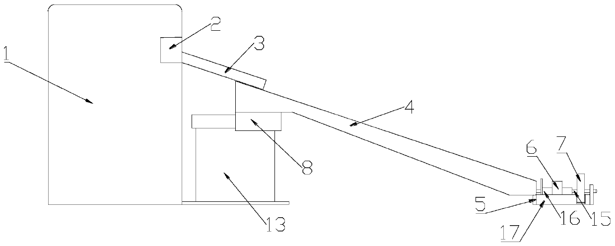
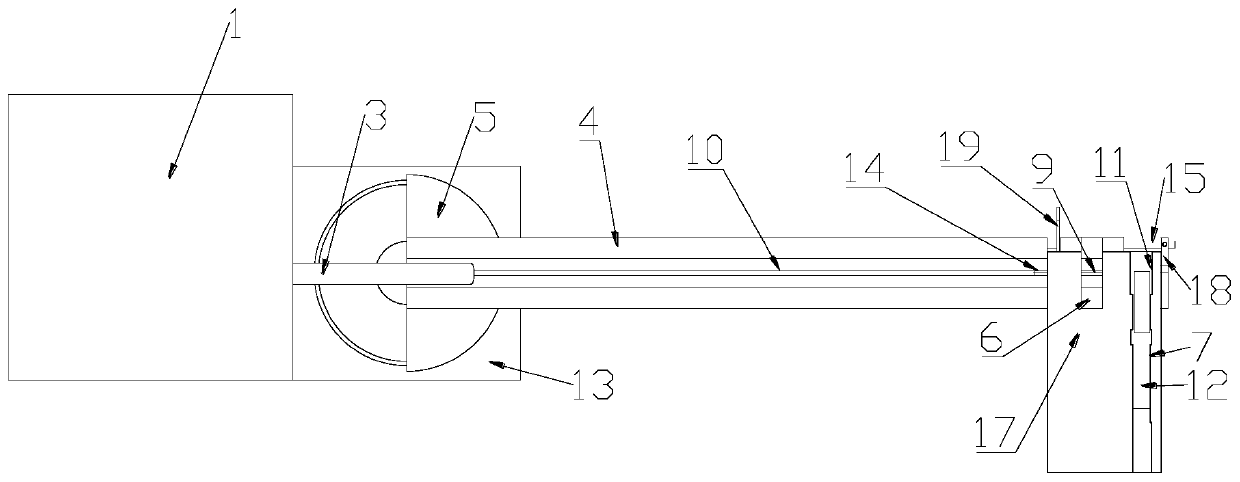
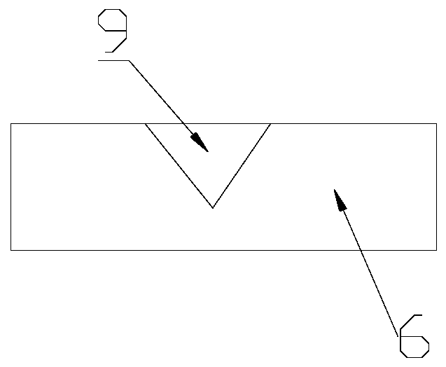

Image

  • Metal filament crimping tool
  • Metal filament crimping tool
  • Metal filament crimping tool

Examples


Embodiment Construction

[0017] The technical solutions of the present invention will be clearly and completely described below in conjunction with the accompanying drawings. Apparently, the described embodiments are some of the embodiments of the present invention, but not all of them. Based on the embodiments of the present invention, all other embodiments obtained by persons of ordinary skill in the art without making creative efforts belong to the protection scope of the present invention.

[0018] In the description of the present invention, it should be noted that the terms "center", "upper", "lower", "left", "right", "vertical", "horizontal", "inner", "outer" etc. The indicated orientation or positional relationship is based on the orientation or positional relationship shown in the drawings, and is only for the convenience of describing the present invention and simplifying the description, rather than indicating or implying that the referred device or element must have a specific orientation, ...


PUM

PropertyMeasurementUnit
angleaaaaaaaaaa
surface roughnessaaaaaaaaaa

Abstract

The invention discloses a metal filament crimping tool. The metal filament crimping tool comprises a conveying circular pipe, a conveying table, a fixing frame, a moving receiving table and a cable lug crimping plier, the conveying circular pipe is arranged obliquely, the conveying table is arranged obliquely, the fixing frame is provided with a sliding rail, the moving receiving table is mountedon the sliding rail and provided with a metal wire storing groove, the conveying table is provided with a metal wire sliding groove, the upper end of the metal wire sliding groove is located on the lower part of the tail end of the conveying circular pipe, one end of the metal wire storing groove can move to the lower part of the lower end the metal wire sliding groove, one end of the cable lug crimping plier is provided with a crimping cavity, the other end of the cable lug crimping plier is provided with a movable handle and a fixed handle, and the other end of the metal wire storing groovecan move to the position by the side of the crimping cavity and directly faces to the crimping cavity. According to the metal filament crimping tool, the working efficiency of crimping a cable lug fora metal filament is improved, the quality problem caused by manual counting and crimping is avoided, meanwhile, the advantage of easy and convenient operation is achieved, and the technological dependence on workers is reduced.

Description

technical field [0001] The invention belongs to the technical field of metal filament crimping, and in particular relates to a metal filament crimping tool. Background technique [0002] Electric slip ring products generally adopt metal contact technology. Compared with the contact method of single contact, multi-contact contact has the advantages of reducing pressure, reducing wear, and increasing service life. At the same time, the probability of jumping pins of the multi-contact electric slip ring decreases geometrically, and the geometric progression of the overall reliability increases. In order to achieve multi-contact contact of electric slip ring products, it is necessary to make metal filaments into bundles, and press-fit wire lugs on the ends of bundled metal filaments. [0003] When the existing processing technology completes the process of pressing the wire nose with bundled metal filaments, the metal filaments are first cut with a wire cutting machine, and the...

Claims


Application Information

Patent Timeline
Patent Type & Authority Applications(China)
IPC IPC(8): B21F15/06
CPCB21F15/06
Inventor 严丰苏慧
Owner 浙江恩碧技创新科技有限公司
Why Eureka
Try Eureka