An assembly device for a valve spring base

A valve spring and assembly device technology, which is applied in assembly machines, metal processing equipment, manufacturing tools, etc., can solve the problems of missing installation, high labor intensity of operators, and multiple installations, so as to achieve convenient installation and use, reliable performance, and avoidance of multiple installations. The effect of loading or missing

Active Publication Date: 2021-06-04
CHONGQING CHANGAN AUTOMOBILE CO LTD
View PDF7 Cites 0 Cited by
  • Summary
  • Abstract
  • Description
  • Claims
  • Application Information

AI Technical Summary

Problems solved by technology

At present, valve spring bases are basically all assembled one by one, such as a valve spring base installation device disclosed in CN102562210A, which includes a housing, a toggle gear, a pressure arm, a return spring, a push-out spring, a push-out baffle and a valve spring base Guide rod; the operator only needs to align the guide rod with the position of the valve spring base, and then press the L-shaped pressure arm to place the valve spring base. Compared with simple manual operation, the work efficiency has been improved, but it can only Installing a valve spring base has the problem of over-installation or missing installation, and the labor intensity of the operator is relatively high

Method used


Image

  • An assembly device for a valve spring base
  • An assembly device for a valve spring base
  • An assembly device for a valve spring base

Examples


Embodiment Construction

[0026] The present invention will be described in detail below in conjunction with the accompanying drawings.

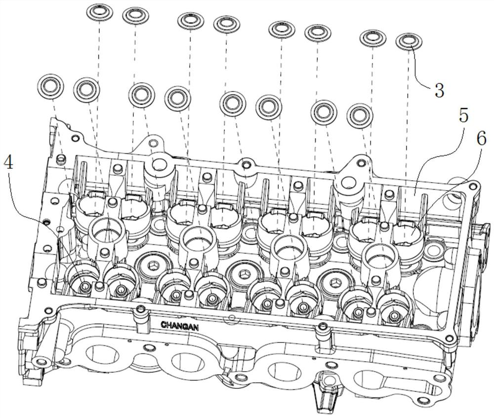
[0027] Such as figure 1 As shown, there are eight valve spring mounting holes 6 on the intake side of the cylinder head 5, and there is a valve guide 4 in each valve spring mounting hole 6, and the eight valve guides 4 are arranged in a row. There are also eight valve spring installation holes 6 on the exhaust side, and there is a valve guide 4 in each valve spring installation hole 6, and the eight valve guides 4 are arranged in a row, and the eight valve guides 4 on the intake side are connected with the exhaust side. The eight valve guides 4 are symmetrically arranged, and the above-mentioned structure of the cylinder head 5 is a prior art. During assembly, eight valve spring bases 3 need to be installed on the eight valve guides 4 on the intake side, and eight valve spring bases 3 are installed on the eight valve guides 4 on the exhaust side.

[0028] Such as ...


PUM


Abstract

The invention discloses an assembly device for a valve spring base, which comprises a collection plate and an assembly tool; the same m rows of blind holes are opened on the collection plate, and the number n of each row of blind holes is the same as the number n of the intake side valves on the cylinder head. The number k of conduits is equal and the arrangement positions are corresponding. The assembly tooling includes a pressing assembly, an elastic connector and an adsorption assembly. The pressing assembly includes a pressing plate and a row of pressing rods. The adsorption assembly includes a support plate, n magnets and a row of sleeves , the support plate is provided with an assembly through hole communicating with the sleeve, n magnets are fixedly connected to the lower ends of the n sleeves, one end of the elastic connector is connected to the pressure plate, and the other end is connected to the support plate, and n pressure rods pass through the The n assembly through holes extend into the n sleeves, and the n magnets can respectively absorb n valve spring bases placed in the n blind holes in each row. By adopting the invention, the assembly of the valve spring base on the intake side or the exhaust side can be completed at one time, avoiding over-assembly or missing assembly, and effectively improving assembly efficiency at the same time.

Description

technical field [0001] The invention relates to an auxiliary assembly device for engine parts, in particular to an assembly device for a valve spring base. Background technique [0002] The valve spring mount is a common engine part that fits into the valve spring mounting hole on the cylinder head through the valve guide. At present, valve spring bases are basically all assembled one by one, such as a valve spring base installation device disclosed in CN102562210A, which includes a housing, a toggle gear, a pressure arm, a return spring, a push-out spring, a push-out baffle and a valve spring base Guide rod; the operator only needs to align the guide rod with the position of the valve spring base, and then press the L-shaped pressure arm to place the valve spring base. Compared with simple manual operation, the work efficiency has been improved, but it can only To install a valve spring base, there is a problem of over-installation or missing installation, and the labor in...

Claims


Application Information

Patent Timeline
Patent Type & Authority Patents(China)
IPC IPC(8): B23P21/00
CPCB23P21/00
Inventor 朱洪磊李加彬尧琼林黄涛张劲松
Owner CHONGQING CHANGAN AUTOMOBILE CO LTD
Why Eureka
Try Eureka