Battery box locking control system and control method
A technology of a control system and a control method, which is applied to charging stations, electric vehicles, vehicle maintenance, etc., can solve the problem that it is difficult for the battery box to control the forward and return travel of the push plate box.
- Summary
- Abstract
- Description
- Claims
- Application Information
AI Technical Summary
Problems solved by technology
Method used
Image

Examples
Embodiment 1
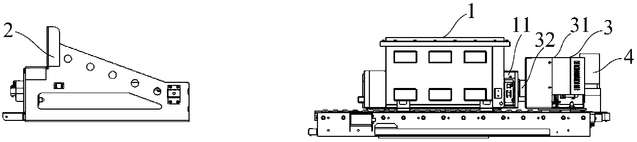
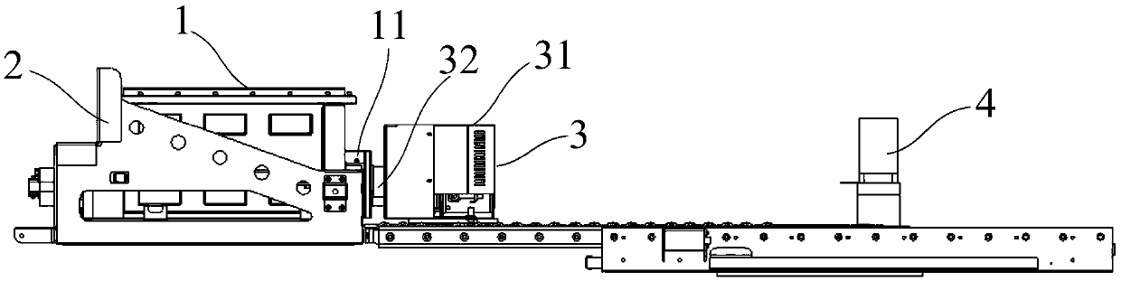
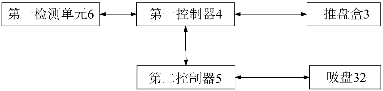
[0066] Such as Figure 1 to Figure 3 Shown is an embodiment of the battery box locking control system of the present invention. The battery box locking control system is used for loading the battery box 1 into the battery compartment 2 . The battery box lock control system includes a push plate box 3, a first controller 4, a second controller 5 and a first detection unit 6, the push plate box 3 includes a push plate box body 31 and a suction cup 32, and the suction cup 32 is telescopically Set on the surface of the push plate box 31, the suction cup 32 of the push plate box 3 is used to fit the battery box 1; the first controller 4 is used to drive the push plate box 3 forward, so that the battery box 1 enters the battery compartment 2 Middle; the second controller 5 is used to switch the push plate box 3 and the battery box 1 in two states of being connected or separated; the first detection unit 6 is used to retract the suction cup 32 to the first predetermined position whe...
Embodiment 2
[0074] Such as Figure 4 As shown, the battery box locking control system in this embodiment is a further improvement on Embodiment 1.
[0075] The battery box lock control system also includes a second detection unit 7, the second detection unit 7 is used to detect whether the push box 3 reaches the first limit position during the return process, and if so, send a first pause signal to the first controller 4 , the first controller 4 is also used to suspend the return of the push tray 3 after receiving the first suspend signal.
[0076] The first limit position is the limit position that the push disk box 3 can reach during the return process. If the push box 3 reaches the first limit position, it means that the push box 3 is abnormal during the return process, and the first controller 4 suspends the return of the push box 3 and enters the abnormal processing stage.
[0077] Wherein, the second detection unit 7 can be a pair of infrared receiver and infrared emitter, and the...
Embodiment 3
[0079] Such as Figure 5 to Figure 6 As shown, the battery box locking control system in this embodiment is a further improvement on Embodiment 1.
[0080] The battery box 1 also includes a lock tongue 12 and a button 13 , the lock tongue 12 is matched with the lock seat 21 of the battery compartment 2 , and the button 13 is connected with the lock tongue 12 . When the battery box 1 is loaded into the battery compartment 2 , the locking tongue 12 of the battery box 1 is stuck in the lock seat 21 of the battery compartment 2 .
[0081] Such as Figure 7 to Figure 8 As shown, the push disc box 3 also includes a push rod 33 and a third controller 34, the third controller 34 is used to control the expansion and contraction of the push rod 33, and the push rod 33 is used to drive the dead bolt 12 to move and reset after the button 13 is pressed. . Wherein, the third controller 34 is communicatively connected with the first controller 4; the first controller 4 is used to send the...
PUM
 Abstract
Description
Claims
Application Information
 - R&D
- Intellectual Property
- Life Sciences
- Materials
- Tech Scout
- Unparalleled Data Quality
- Higher Quality Content
- 60% Fewer Hallucinations
Browse by: Latest US Patents, China's latest patents, Technical Efficacy Thesaurus, Application Domain, Technology Topic, Popular Technical Reports.
© 2025 PatSnap. All rights reserved.Legal|Privacy policy|Modern Slavery Act Transparency Statement|Sitemap|About US| Contact US: help@patsnap.com