Clamping mechanism for clamping and replacing diaphragm

A clamping mechanism and diaphragm technology, applied in the field of cave engineering, can solve the problems of lower test efficiency, hidden safety hazards, pollution, etc.

Pending Publication Date: 2022-03-01
ZHENGZHOU RES INST OF MECHANICAL ENG CO LTD
View PDF0 Cites 0 Cited by
  • Summary
  • Abstract
  • Description
  • Claims
  • Application Information

AI Technical Summary

Problems solved by technology

The hydraulic clamping mechanism uses a part of the pipe section as the piston in the hydraulic cylinder, and realizes the clamping and loosening of the diaphragm by adjusting the pressure difference inside the piston. The device is simple and the clamping force is large, but the size of the mechanism is large, and the manufacturing cost and The maintenance cost is high. At the same time, due to the large size, the sealing area is relatively large. Once the seal is partially damaged or worn, the overall seal will fail, and the pressure

Method used


Image

  • Clamping mechanism for clamping and replacing diaphragm
  • Clamping mechanism for clamping and replacing diaphragm
  • Clamping mechanism for clamping and replacing diaphragm

Examples


Embodiment Construction

[0037] The present invention will be further described below in conjunction with embodiment (accompanying drawing):

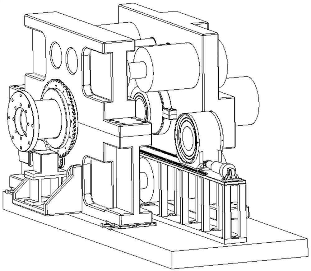
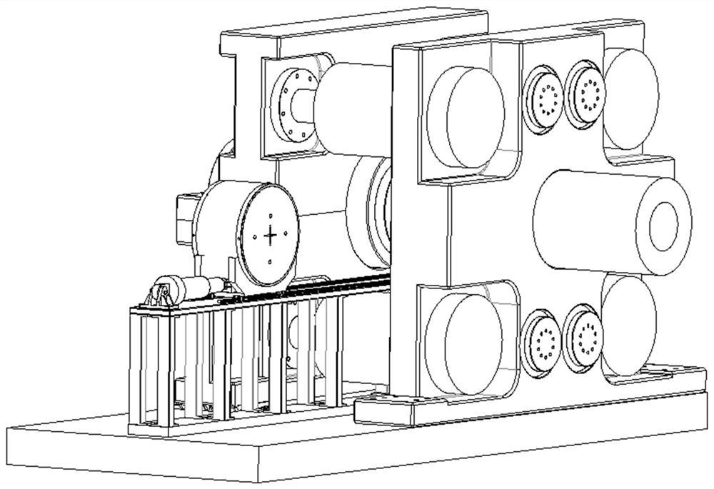
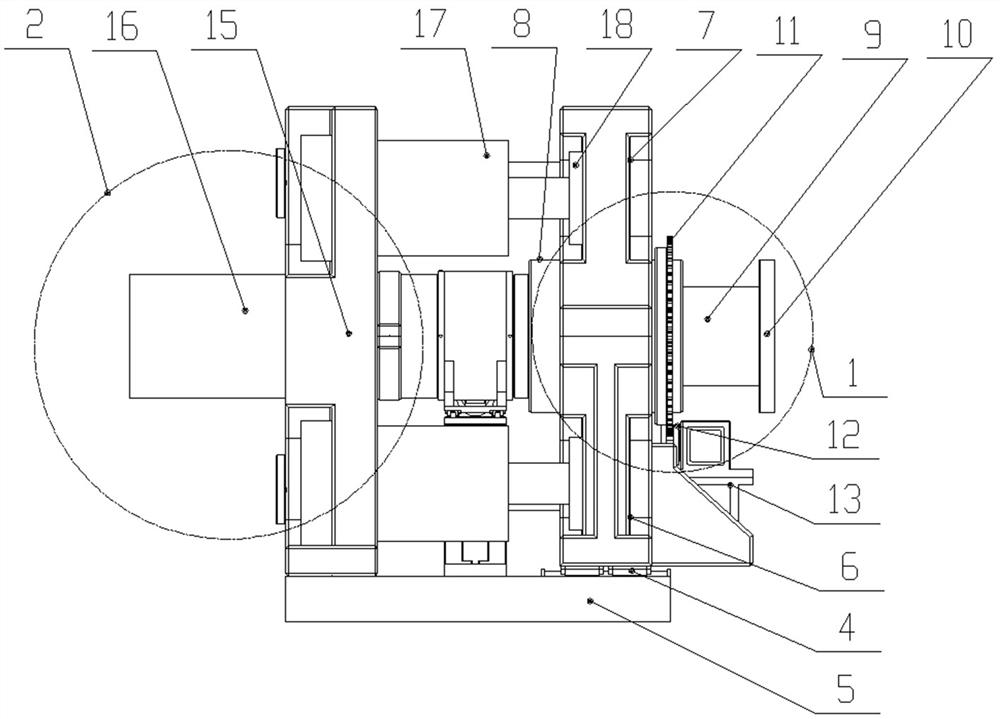
[0038] Such as figure 1 , 2 , 3, and 4, the clamping mechanism for diaphragm clamping and replacement of the present invention includes the driving segment clamping mechanism 1, the driven segment clamping mechanism 2 and the driving segment clamping mechanism arranged in sequence from left to right. Mechanism 1, the diaphragm replacement mechanism 3 between the clamping mechanism 2 of the driven section;

[0039]a. The driving section clamping mechanism 1 includes the linear guide rail 4 arranged horizontally through the front and rear ends of the bottom, the lower part 6 of the driving support seat installed on the foundation 5 by several sets of sliders, the upper part 7 of the driving support seat and the lower part 7 of the driving support seat They are connected by fixed connectors, and the two form an integral drive support base (see Figure 6 , 7 ),...


PUM


Abstract

A clamping mechanism for clamping and replacing a diaphragm adopts a split type structural design and comprises a driving section clamping mechanism, a driven section clamping mechanism and a diaphragm replacing mechanism which are sequentially designed from left to right, and the diaphragm replacing mechanism is located between the driving section clamping mechanism and the driven section clamping mechanism. The driving section clamping mechanism can achieve axial feeding of pipelines and can also achieve axial displacement of the whole supporting seat, the driven section clamping mechanism achieves axial position fixing of butt-joint pipelines, and the diaphragm replacing mechanism achieves clamping and replacing of diaphragms between two pipelines. Reliable sealing and clamping among the driving section, the diaphragm and the driven section can be achieved through cooperation of the driving section, the diaphragm and the driven section, and safety and reliability of the whole test pipeline are guaranteed. On the driving form of each degree of freedom, the design which is simple in structure and convenient to install and debug is adopted, effective adjustment of displacement between the pipeline and the diaphragm is guaranteed, and the space utilization rate can be fully improved. According to the design of the structural form, all the mechanisms are relatively independent, interference among the mechanisms is small, the structure is simple, operation is convenient, and efficiency is high.

Description

technical field [0001] The invention relates to the field of cave engineering, and is applicable to a mechanism for reliably clamping and releasing diaphragms of different thicknesses under different test environments. Background technique [0002] At present, the cave body is widely used in the tests of various flight models. In the cave, different sections of the equipment are separated by diaphragms, and each section is connected by a diaphragm clamping mechanism, and diaphragms of different thicknesses are clamped by the clamping mechanism to meet the test requirements. [0003] Most of the existing clamping mechanisms adopt flange-type clamping mechanisms, hydraulic clamping mechanisms, full-thread clamping mechanisms, and cut-off thread clamping mechanisms. The hydraulic clamping mechanism uses a part of the pipe section as the piston in the hydraulic cylinder, and realizes the clamping and loosening of the diaphragm by adjusting the pressure difference inside the pis...

Claims


Application Information

Patent Timeline
IPC IPC(8): G01M9/04G01M9/02
CPCG01M9/04G01M9/02
Inventor 郭永才卢志辉郑国良张磊乐游广飞牛建涛高超峰马千里
Owner ZHENGZHOU RES INST OF MECHANICAL ENG CO LTD
Why Eureka
Try Eureka