Magnetic head and its mfg. method

A manufacturing method and magnetic head technology, which is applied in the direction of magnetic recording head, manufacturing magnetic head surface, manufacturing magnetic head with a structure composed of multiple magnetic heads, etc., can solve the problems of small fixing force, distortion of residual stress, deterioration of magnetic characteristics, etc., and achieve guaranteed position relationship, preventing uneven effects

Inactive Publication Date: 2004-03-10
ALPS ALPINE CO LTD
View PDF0 Cites 4 Cited by
  • Summary
  • Abstract
  • Description
  • Claims
  • Application Information

AI Technical Summary

Problems solved by technology

[0011] use Figure 13 In the shown structure, even if each convex portion 130a-132a is embedded and fixed in the slit-shaped through-hole 135-137, the fixing force caused by each convex portion 130a-132a embedded and fixed in the slit-shaped through-hole 135-137 is not significant. Large, the fixing force in this mating state is not stable, so it is necessary to dry and cure after applying the adhesive to really fix it
[0012] In addition, when the half magnetic core 130, 131 or the sealing plate 132 is pressed into the shape perforations 135-137, not only the fixing strength of the half magnetic core 130, 131 or the sealing plate 132 is not sufficient, but also causes the half magnetic core 130, 131 or the sealing Distortion of residual stress of plate 132 or deterioration of magnetic properties

Method used


Image

  • Magnetic head and its mfg. method
  • Magnetic head and its mfg. method
  • Magnetic head and its mfg. method

Examples


Embodiment Construction

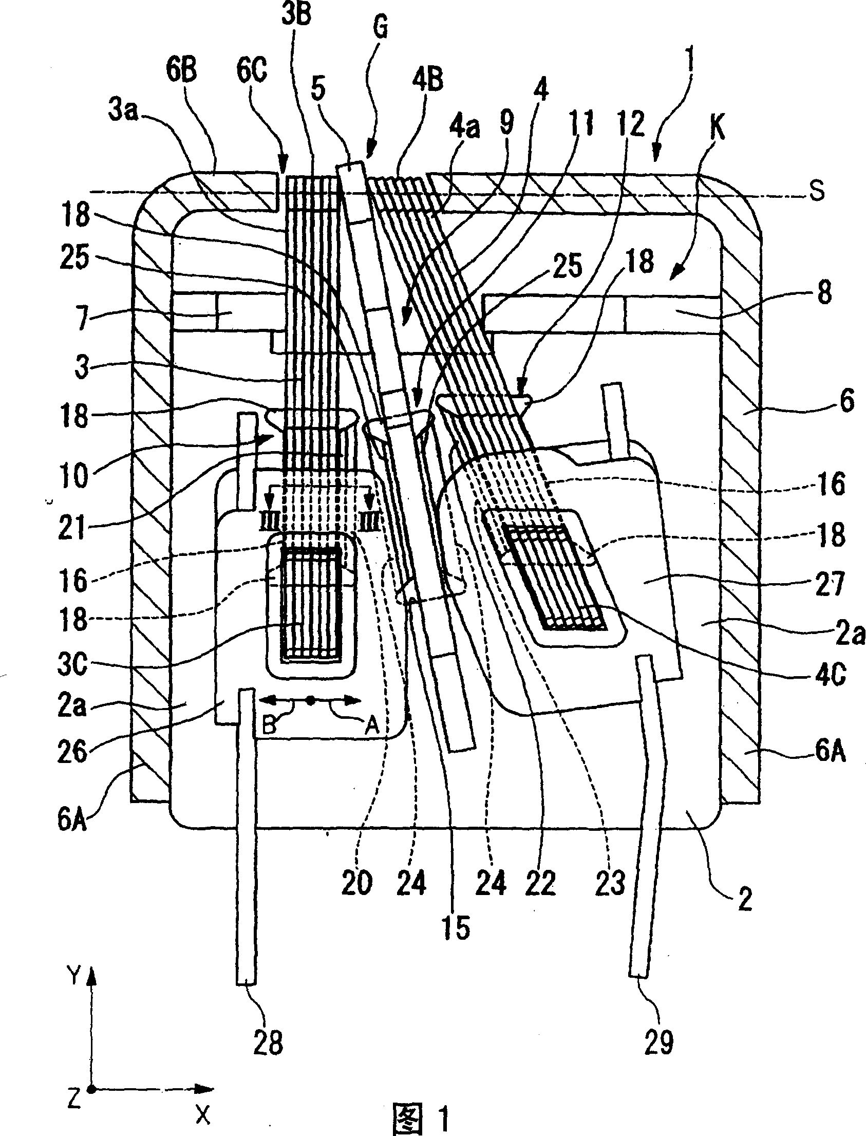
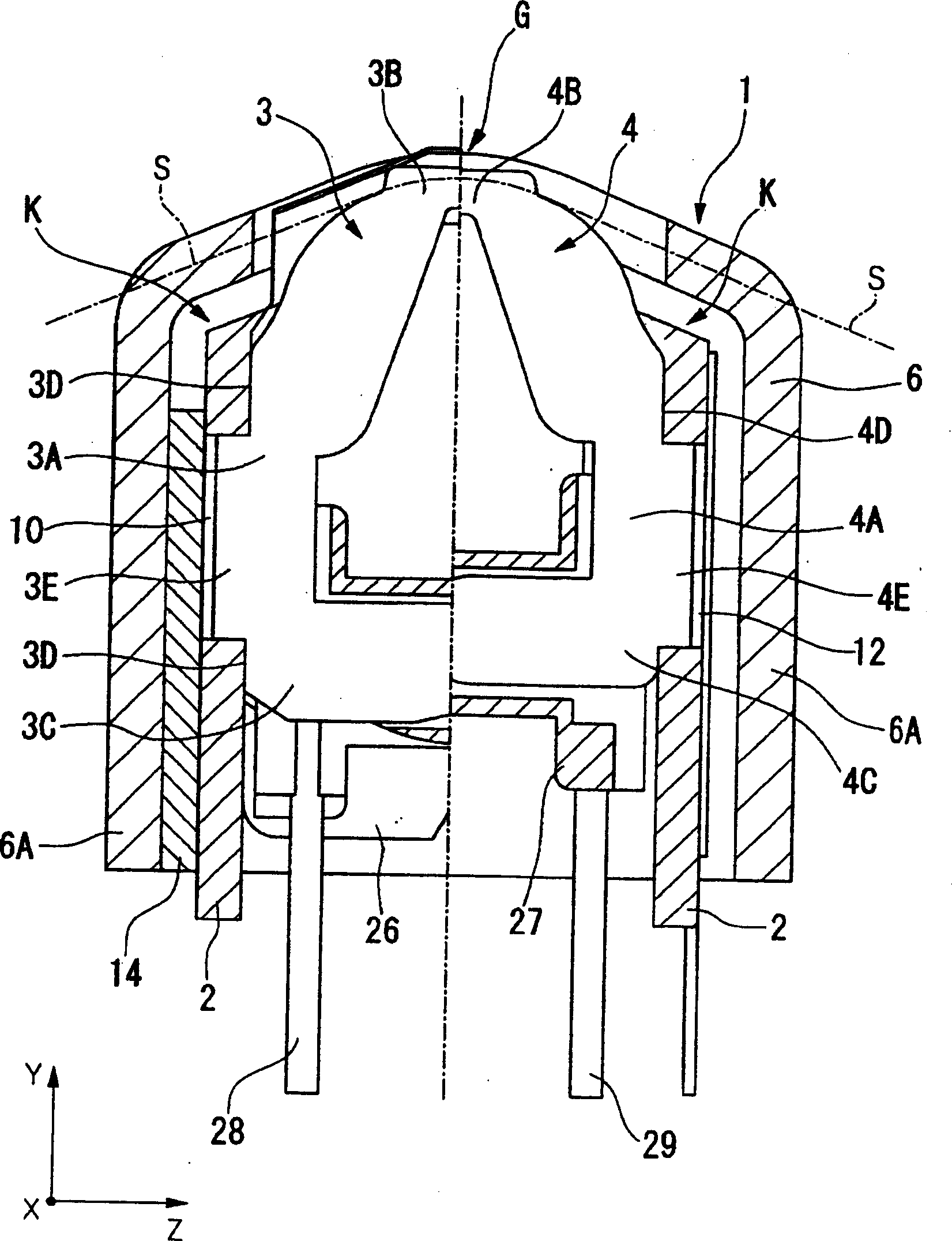
[0087] Next, the magnetic head and its manufacturing method according to the first embodiment of the present invention will be described with reference to the drawings.

[0088] As shown in FIGS. 1 and 2 , the magnetic head 1 of the present embodiment is composed of two magnetic core assemblies K mounted in a sealed case 6. Magnetic core assembly K of the magnetic core halves 3 , 4 and the sealing plate 5 .

[0089] In this embodiment, the above-mentioned airtight casing 6 is composed of a square barrel peripheral wall 6A and a front wall 6B formed in a shape that closes the opening on one side of the peripheral wall 6A, and is integrally formed by deep drawing (deep drawing processing) of a metal material. A window portion 6C is formed on a part of the front wall 6B. Additionally, Figure 1 and figure 2 The shown cross-sectional shape of the magnetic head shows the state before the grinding of the front wall 6B of the sealed case 6 along the grinding line S is completed. B...


PUM


Abstract

In a magnetic head according to the present invention, a base is provided with at least one first positioning hole and a magnetic core half has a back portion which is disposed in the first positioning hole. In addition, the base is further provided with at least one first recess at the periphery of the first positioning hole and the base is partially deformed due to the first recess such that a portion of the base at the periphery of the first positioning hole is shifted to press the back portion of the magnetic core half against an inner side of the first positioning hole. Accordingly, the present invention provides a magnetic head in which the magnetic core half can be reliably fixed to the base and a method for manufacturing the magnetic head.

Description

technical field [0001] The present invention relates to a magnetic head and a method of manufacturing the magnetic head. Background technique [0002] As an example of a dual-channel re-recording type magnetic head for audio, as shown in FIG. The component 102 is housed in a sealed case 105 to form a magnetic head 106 . [0003] There are circular protrusions 108, 109 on the base part 102, and the above-mentioned half magnetic cores 100, 101 and The state of the sealing plate 112 inserted therebetween (half magnetic core) is fixed. That is, the half magnetic core 100 is sandwiched between one convex portion 108 and the locking (hooking) piece 110, and the half magnetic core 101 is sandwiched between the other convex portion 109 and the other locking piece 111; the sealing plate 112 They are sandwiched between the magnetic core halves 100, 101 and between the above-mentioned convex parts 108, 109, respectively. [0004] Then, the tip portions of these half magnetic cores ...

Claims


Application Information

Patent Timeline
Patent Type & Authority Applications(China)
IPC IPC(8): G11B5/10G11B5/105G11B5/11G11B5/127G11B5/187G11B5/23G11B5/29
CPCG11B5/232G11B5/10G11B5/1272G11B5/112G11B5/105G11B5/295G11B5/1871G11B5/127
Inventor 阿部正富
Owner ALPS ALPINE CO LTD
Why Eureka
Try Eureka