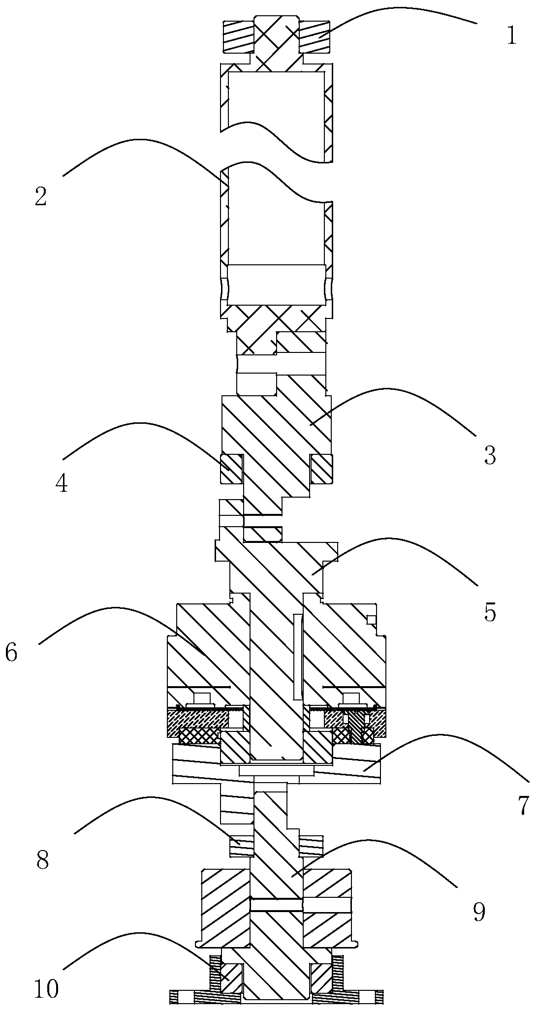
Transmission mechanism capable of automatically adjusting concentricity and swing door

A technology of automatic adjustment and transmission mechanism, applied in the field of transmission, can solve the problems of large wear of the mechanism due to centrifugal force and shortened life of the mechanism

Inactive Publication Date: 2020-03-17
PCI TECH & SERVICE CO LTD +3
View PDF0 Cites 0 Cited by
  • Summary
  • Abstract
  • Description
  • Claims
  • Application Information

AI Technical Summary

Problems solved by technology

[0003] Because the height of the whole mechanism is relatively high, if the transmission mechanism does not adjust and control the concentricity of the flapping door, the centrifugal force generated during the high-speed rotation of the whole mechanism will cause great wear and tear on the mechanism, and the life of the mechanism will be shortened

Method used


Image

  • Transmission mechanism capable of automatically adjusting concentricity and swing door

Examples


Embodiment Construction

[0026] In order to make the technical problems solved by the present invention, the technical solutions adopted and the technical effects achieved clearer, the technical solutions of the embodiments of the present invention will be further described in detail below in conjunction with the accompanying drawings. Obviously, the described embodiments are only the technical solutions of the present invention. Some, but not all, embodiments. Based on the embodiments of the present invention, all other embodiments obtained by those skilled in the art without creative efforts fall within the protection scope of the present invention.

[0027] In the description of the present invention, unless otherwise clearly stipulated and limited, the terms "connected" and "fixed" should be understood in a broad sense, for example, it can be fixed connection, detachable connection or integration; it can be mechanical connection , can also be an electrical connection; it can be a direct connection...


PUM


Abstract

The invention discloses a transmission mechanism capable of automatically adjusting concentricity. A clutch is freely arranged, a first self-aligning bearing is arranged on a first transmission system, and a second self-aligning bearing is arranged at the end, far away from the first transmission system, of a second transmission system. The concentricity between a transmission shaft of the first transmission system and the clutch can be automatically adjusted by arranging the first self-aligning bearing in the first transmission system, the end, far away from a clutch type main shaft, of the first transmission system is ensured to be vertically mounted, the concentricity between the second transmission system and the clutch can be automatically adjusted by arranging the second self-aligning bearing in the second transmission system, the position where the second transmission system is connected with the clutch is ensured to be vertically mounted, and therefore the concentricity of thewhole transmission mechanism can be automatically adjusted through one-by-one adaptability of the three parts.

Description

technical field [0001] The invention relates to the field of transmission technology, in particular to a transmission mechanism capable of automatically adjusting concentricity and a flapping door. Background technique [0002] At present, the flapping door unit is widely used in the fields of access control, automatic ticket checking equipment, and rail transit equipment. The flapping door unit is an AFC special module integrating optical, mechanical and electrical technologies. It is installed in the gate and acts as a blocking mechanism to effectively control the entry and exit behavior of pedestrians and passengers. Only those with legal authorization are allowed to pass. Provide fast ticket check-in and entry-exit services for passengers. [0003] Because the height of the whole mechanism is relatively high when flapping the door, if the transmission mechanism does not adjust and control the concentricity, the centrifugal force generated during the high-speed rotation ...

Claims


Application Information

Patent Timeline
Patent Type & Authority Applications(China)
IPC IPC(8): F16H57/022F16H57/02E01F13/04
CPCE01F13/04F16H57/02F16H57/022F16H2057/02039F16H2057/0225
Inventor 李茂张俊明彭树林
Owner PCI TECH & SERVICE CO LTD
Why Eureka
Try Eureka