Air-fuel annular heat exchanger for aero-engine

An aero-engine and heat exchanger technology, applied in indirect heat exchangers, heat exchanger types, heat exchanger shells, etc., can solve problems such as inability to adapt to the requirements of new engines, and achieve a reasonable design structure and uniform flow field distribution. Effect

Active Publication Date: 2021-06-08
XINXIANG AVIATION IND GROUP
View PDF7 Cites 0 Cited by
  • Summary
  • Abstract
  • Description
  • Claims
  • Application Information

AI Technical Summary

Problems solved by technology

At present, the traditional engine matching heat exchanger can no longer meet the requirements of new engines

Method used


Image

  • Air-fuel annular heat exchanger for aero-engine
  • Air-fuel annular heat exchanger for aero-engine
  • Air-fuel annular heat exchanger for aero-engine

Examples


Embodiment Construction

[0028] Below in conjunction with accompanying drawing and embodiment the present invention will be further described:

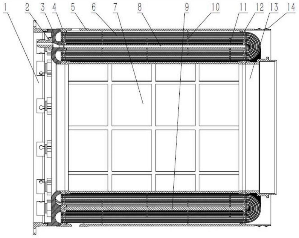
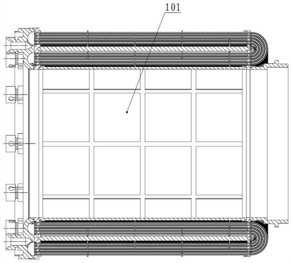
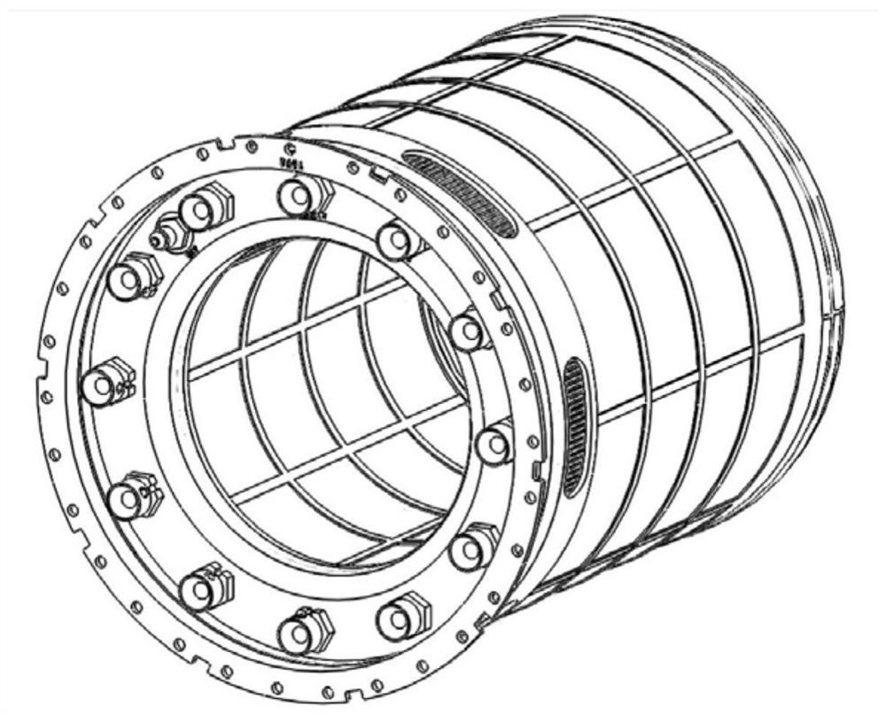
[0029] Such as figure 1 As shown, it is a schematic structural diagram of the air-fuel annular heat exchanger of this embodiment, including a mounting flange 1, a test pipe joint 2, an annular cavity 3, a front end plate 4, an outer cylinder 5, a heat exchange tube 6, an inner cylinder 7, Test tube 8, positioning rod 9, partition I10, partition II11, rear end plate 12, inner cylinder tail section 13, outer cylinder 5 spring pieces 14. Such as figure 2 As shown, the front end plate 4, the heat exchange tube 6, the inner tube 7, the test tube 8, the positioning rod 9, the partition I10, the partition II11, the rear end plate 12, the ring cavity 3, and the inner tube tail section 13 constitute the heat exchanger core Body 101. The heat exchanger core 101, the mounting flange 1, the test pipe joint 2, and the spring leaf 14 form an air-fuel annular heat excha...


PUM


Abstract

The invention discloses a novel air-fuel annular heat exchanger for an aero-engine, comprising a heat exchanger core body, a test pipe joint, and an outer cylinder, and the heat exchanger core body includes a front end plate, a rear end plate, and several heat exchange tubes , test tubes, several positioning rods, several baffles I, several baffles II, an inner cylinder, and an annular cavity. In other cases, the demand for high-vibration levels is problematic.

Description

technical field [0001] The invention belongs to the technical field of heat exchanger structure design, and relates to an air-fuel annular heat exchanger suitable for ultra-high temperature and high pressure working conditions, high integration requirements, and high vibration level requirements. Background technique [0002] With the development of the field of aero-engines, the performance requirements of aero-engine heat exchangers are getting higher and higher, mainly manifested in: high integration requirements; new thermal cycle requirements, that is, ultra-high temperature and high pressure conditions; high vibration level needs. At present, the traditional engine supporting heat exchanger can no longer meet the requirements of new engines. Therefore, the present invention proposes an annular heat exchanger with a novel structure, which can meet the requirements of new engines. Contents of the invention [0003] The purpose of the present invention is to provide a...

Claims


Application Information

Patent Timeline
Patent Type & Authority Patents(China)
IPC IPC(8): F28D7/06F28F9/24
CPCF28D7/06F28F9/24
Inventor 梁家骏闫兆允张雅丹申言森翟学阳徐思远卞佳明齐思琪魏豪王兴远
Owner XINXIANG AVIATION IND GROUP
Why Eureka
Try Eureka