Printing ink stirring device

A technology of stirring device and ink, applied in the directions of mixer accessories, transportation and packaging, dissolving, etc., can solve the problems of low stirring efficiency of ink stirring device, and achieve the effect of improving stirring efficiency and improving stirring quality.

Inactive Publication Date: 2020-03-24
安徽华谊日新科技有限公司
View PDF1 Cites 0 Cited by
  • Summary
  • Abstract
  • Description
  • Claims
  • Application Information

AI Technical Summary

Problems solved by technology

[0004] The technical problem to be solved in the present invention is to provide an ink stirring device for the above defects, including a support base, a stirring tank is fixedly connected to the support base, a rotating stirring unit is arranged in the stirring tank, and an observation window is provided on the side of the mixing tank. The mixing tank is also equipped with an upper and lower mixing unit for driving the rotating mixing unit to move up and down. The rotating mixing unit is provided with a push plate to push the material in the mixing tank to roll up and down. Connected to the support seat to solve the problem of low stirring efficiency of the ink stirring device in the prior art

Method used


Image

  • Printing ink stirring device
  • Printing ink stirring device
  • Printing ink stirring device

Examples


Embodiment 1

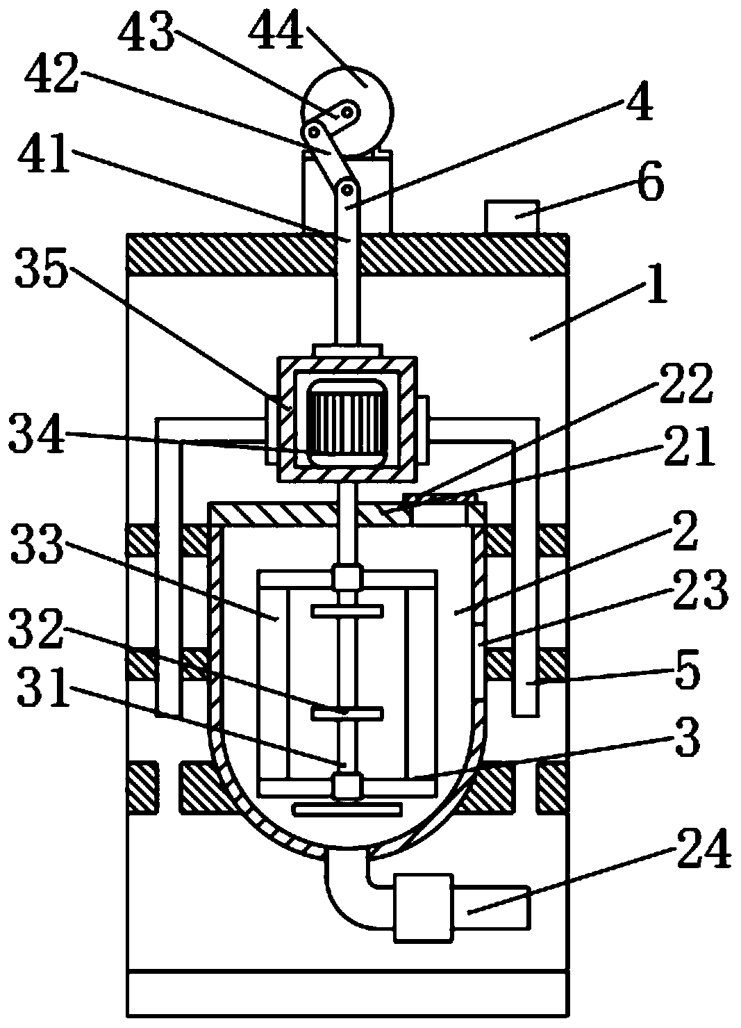
[0023] Depend on figure 1 As shown, a kind of ink stirring device comprises a support base 1, a stirring tank 2 and a timer 6 are fixedly connected to the support base 1, a rotating stirring unit 3 is arranged in the stirring tank 2, and a stirring motor 34 on the rotating stirring unit 3 is connected with The timer 6 is fixedly connected, and the side of the stirring tank 2 is provided with an observation window 23. The stirring tank 2 is also provided with an up and down stirring unit 4 for driving the rotating stirring unit 3 to move up and down. The push plate 32 for the material to roll up and down, the rotating stirring unit 3 is fixedly connected to the upper and lower stirring unit 4, and the upper and lower stirring unit 4 is fixedly connected to the support base 1;

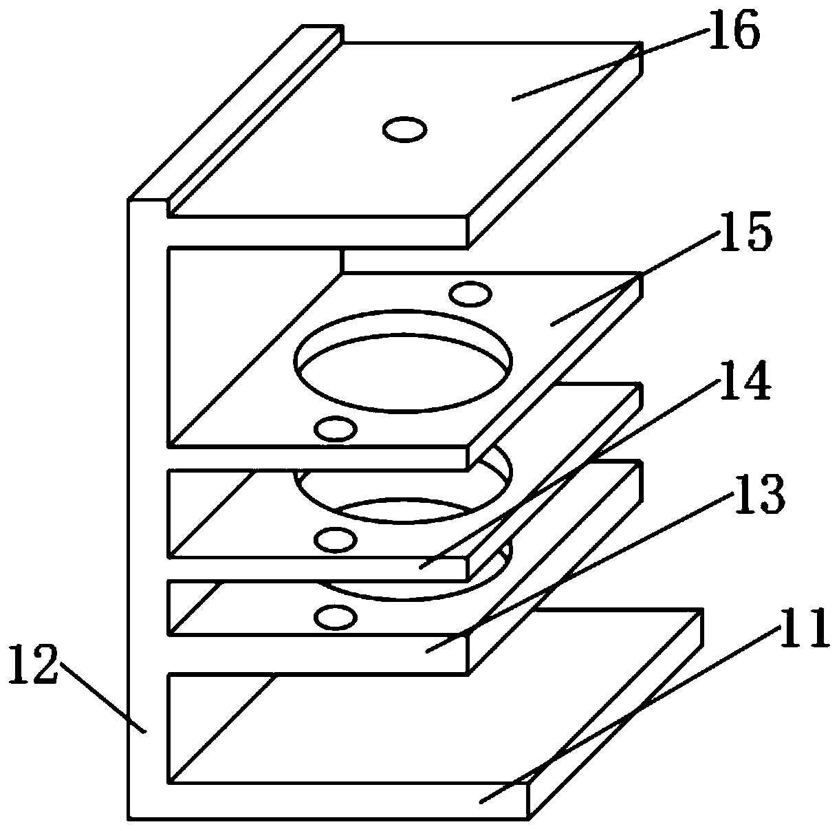
[0024] like image 3 As shown, the support seat 1 includes a bottom support seat 11 and a side support plate 12, the bottom support seat 11 and the side support plate 12 are arranged in an L shape, and ...

Embodiment 2

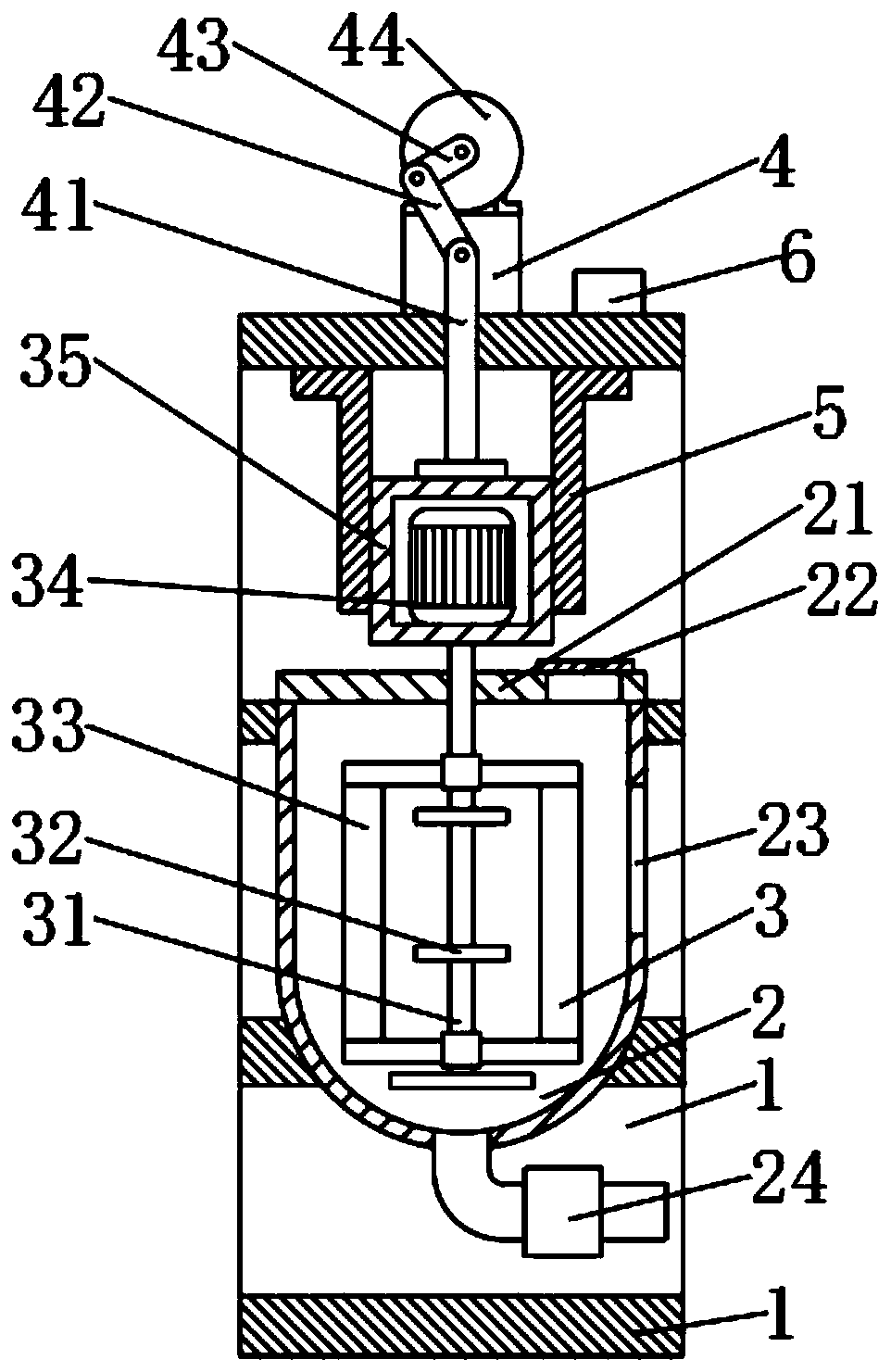
[0033] Depend on figure 2 As shown, a kind of ink stirring device comprises a support base 1, a stirring tank 2 and a timer 6 are fixedly connected to the support base 1, a rotating stirring unit 3 is arranged in the stirring tank 2, and a stirring motor 34 on the rotating stirring unit 3 is connected with The timer 6 is fixedly connected, and the side of the stirring tank 2 is provided with an observation window 23. The stirring tank 2 is also provided with an up and down stirring unit 4 for driving the rotating stirring unit 3 to move up and down. The push plate 32 for the material to roll up and down, the rotating stirring unit 3 is fixedly connected to the upper and lower stirring unit 4, and the upper and lower stirring unit 4 is fixedly connected to the support base 1;

[0034] In this embodiment, the limiting unit 5 is an L-shaped metal plate, and the limiting unit 5 is fixedly connected to the bottom of the fourth support plate 16. There are two limiting units 5, which ...


PUM


Abstract

The invention discloses an ink stirring device, belonging to the technical field of ink stirring. The ink stirring device overcomes the problem that conventional ink stirring devices are low in stirring efficiency is solved. According to main technical points in the invention, the ink stirring device is characterized by comprising a supporting seat, wherein the supporting seat is fixedly connectedwith a stirring tank; a rotary stirring unit is arranged in the stirring tank; an observation window is formed in the side surface of the stirring tank; an up-and-down stirring unit for driving the rotary stirring unit to move up and down is arranged on the stirring tank; a pushing plate for pushing materials in the stirring tank to roll up and down is arranged on the rotary stirring unit; the rotary stirring unit is fixedly connected to the up-and-down stirring unit; and the up-and-down stirring unit is fixedly connected to the supporting seat. According to the invention, stirring of ink inthe stirring tank is driven by the rotary stirring unit and the up-and-down stirring unit, vortexes in the stirring process are destroyed, and the stirring efficiency of the ink is improved.

Description

technical field [0001] The invention relates to the technical field of ink stirring, in particular to an ink stirring device. Background technique [0002] In the printing process, inks of different colors need to be used. In the production process of the ink, in order to ensure that the ink is mixed evenly, it is necessary to use a stirring device to stir the ink. The traditional stirring device cannot fully stir the ink, and it is easy to appear due to uneven stirring. The resulting ink color is impure, which reduces the production quality, increases the proportion of unqualified products, increases the cost and brings inconvenience to the user. [0003] Chinese Patent Publication No. "CN108543436A" discloses an ink stirring device for printing equipment, including a machine body, the middle part of the top of the machine body is fixedly connected with a first motor, the output shaft of the first motor runs through and extends to the inside of the machine body, and is fixe...

Claims


Application Information

Patent Timeline
Patent Type & Authority Applications(China)
IPC IPC(8): B01F11/00B01F15/00
CPCB01F31/441B01F35/2216B01F35/514B01F2101/35
Inventor 沈希军
Owner 安徽华谊日新科技有限公司
Why Eureka
Try Eureka