Gravity type roller crushing and separating machine

A separator and gravity-type technology, which is applied in the direction of solid separation, filter screen, grille, etc., can solve the problems of reducing product quality and crushing efficiency, and can not discharge fine materials, so as to achieve the effect of improving quality and crushing efficiency

Pending Publication Date: 2020-03-24
ANXIN TUORI INFORMATION TECH CO LTD
View PDF0 Cites 0 Cited by
  • Summary
  • Abstract
  • Description
  • Claims
  • Application Information

AI Technical Summary

Problems solved by technology

[0004] Based on the above problems, the present invention provides a gravity drum crushing and separating machine, which is used to solve the problem that the fine materials cannot be discharged in time when crushing finished products such as alloy balls in the prior art, thereby reducing product quality and crushing efficiency. question

Method used


Image

  • Gravity type roller crushing and separating machine
  • Gravity type roller crushing and separating machine
  • Gravity type roller crushing and separating machine

Examples


Embodiment 1

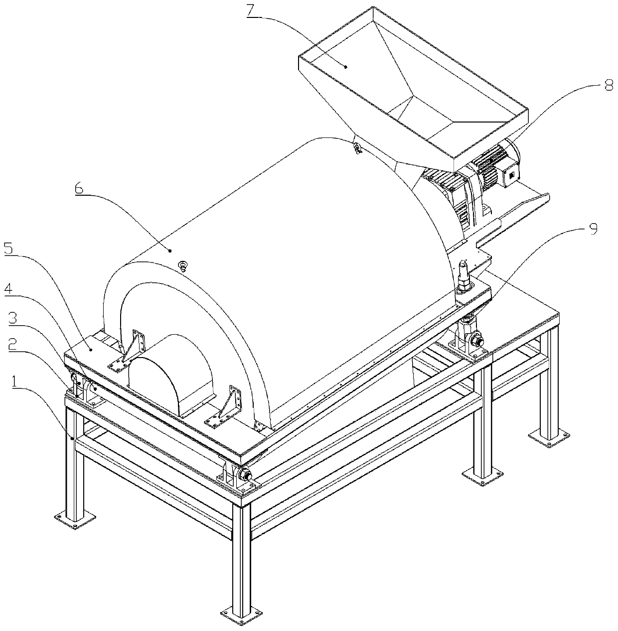
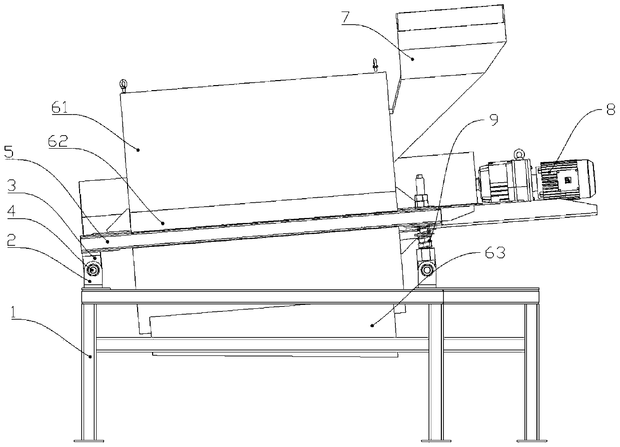
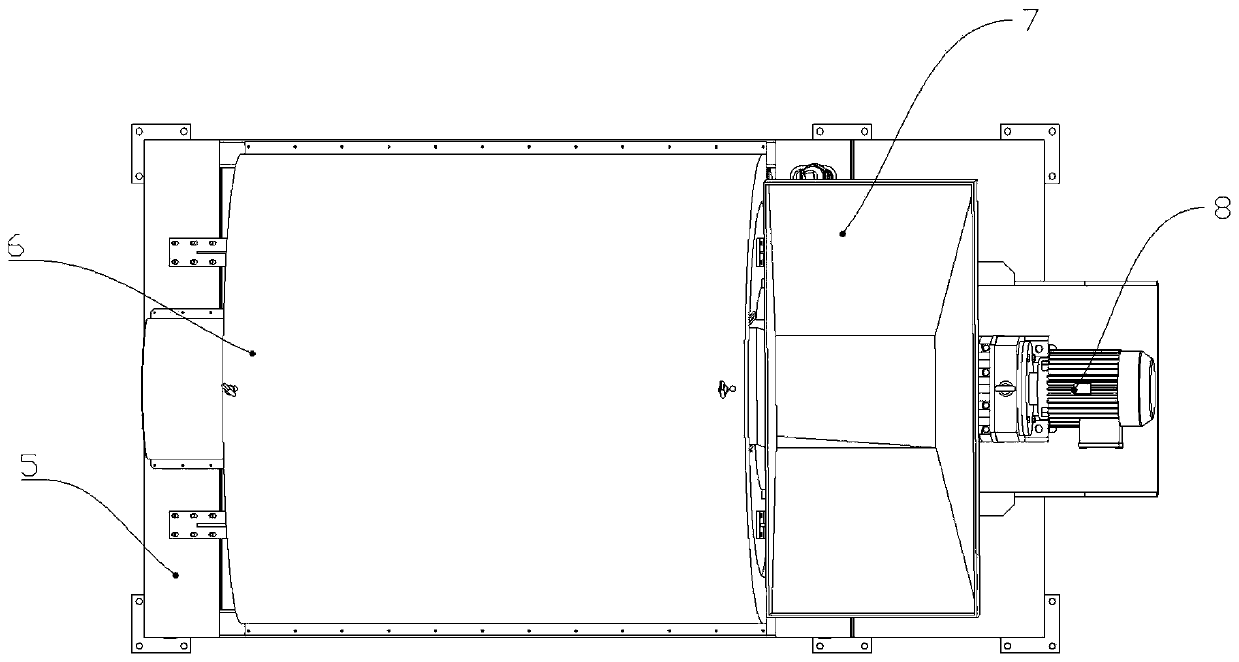
[0037] Such as Figure 1-11 As shown, a gravity drum crushing and separating machine includes a support frame assembly, a rotating mechanism 8 is installed on one side of the top surface of the supporting frame assembly, and a right flange 10 is connected to the end surface of the rotating mechanism 8, and a right flange 10 is installed on the right flange 10. Mesh sieve cylinder 11, the other end of the mesh sieve cylinder 11 is connected with a left flange 16, a crushing mechanism located in the mesh sieve cylinder 11 is installed between the left flange 16 and the right flange 10, and the side of the left flange 16 is connected with a The driving shaft 13 and the driven shaft 13 are installed in the bearing 14 on the other side of the support frame assembly. The support frame assembly is equipped with a cover assembly covering the screen cylinder 11. The lower end of the cover assembly has a discharge groove 621 to support The right closing part that can close the right fla...

Embodiment 2

[0040] Such as Figure 1-11 As shown, on the basis of the above-mentioned embodiments, this embodiment provides a preferred structure of the crushing mechanism. That is, the crushing mechanism includes a collision plate 17 and a collision bar 18 installed between the left flange 16 and the right flange 10. With the rotation of the screen cylinder 11, finished products such as alloy balls collide with the collision plate 17 and the collision bar 18 to form a crushing mechanism. Finished products such as alloy balls are broken.

[0041] Preferably, the number of collision plates 17 and collision bars 18 is multiple, and a plurality of collision bars 18 and a plurality of collision plates 17 are all evenly installed on the inner wall of the screen cylinder 11, so that when the screen cylinder 11 rotates, , The collision plate 17 and the collision rod 18 can evenly impact finished products such as alloy balls.

[0042] The remaining parts are the same as those in Embodiment 1, so ...

Embodiment 3

[0044] Such as Figure 1-11 As shown, on the basis of the above embodiments, this embodiment provides a preferred structure of the rotating mechanism. That is, the rotating mechanism 8 includes a motor 81 installed on the top surface of the support frame assembly, the motor 81 is connected with a drive shaft 82 , the drive shaft 82 is connected with a right end 83 , and the right end 83 is connected with the right flange 10 . The rotation of the motor 81 drives the driving shaft 82 to rotate, and the rotation of the driving shaft 82 drives the right end 83 and the right flange 10 to rotate in turn, and the right flange 10 drives the screen cylinder to rotate again.

[0045] Preferably, the right closure includes a right end plate 12 installed on the support frame assembly, the middle part of the right end plate 12 has a round hole 121, and the main shaft passes through the round hole 121; the left closure includes a left end plate installed on the support frame assembly 19. T...


PUM


Abstract

The invention relates to the technical field of crushing and separating machines, in particular to a gravity type roller crushing and separating machine. The crushing and separating machine is used for solving the problems that in the prior art, when finished products such as alloy balls are crushed, fine materials cannot be discharged in time, so that the product quality and the crushing efficiency are reduced. The crushing and separating machine comprises a right flange, wherein a mesh screen cylinder is mounted on the right flange, the other end of the mesh screen cylinder is connected witha left flange, a crushing mechanism located in the mesh screen cylinder is mounted between the left flange and the right flange, an outer cover assembly covering the mesh screen drum is mounted on asupport frame assembly, and a discharge groove is formed in the lower end of the outer cover assembly. According to the crushing and separating machine, the finished products such as the alloy balls are put into the mesh screen cylinder to be crushed, the crushed fine materials can be timely removed from the gap of the mesh screen cylinder due to the action of gravity and leaked out of the discharge groove, so that the fine materials do not need to be crushed again, and the quality and the crushing efficiency of the product can be improved.

Description

technical field [0001] The invention relates to the technical field of crushing and separating machines, in particular to a gravity drum crushing and separating machine. Background technique [0002] When the finished alloy ball is crushed, corresponding crushers are needed. These crushers break the bulk material into smaller pieces to achieve the desired finished alloy ball or other materials. [0003] In the prior art, there are mainly jaw crushers, impact crushers, etc. for crushing finished alloy balls, and when jaw crushers, impact crushers, etc. crush alloy balls, a large amount of fine materials will be produced. Fine materials or qualified products cannot be discharged in time, and the crusher will further crush these fine materials, which seriously affects the product quality and work efficiency. Therefore, we urgently need a crushing separator that can discharge fine materials in time, thereby improving product quality and crushing efficiency. Contents of the in...

Claims


Application Information

Patent Timeline
Patent Type & Authority Applications(China)
IPC IPC(8): B02C19/00B02C23/16B07B1/22B07B1/42B07B1/46
CPCB02C19/005B02C23/16B02C2023/165B07B1/22B07B1/42B07B1/46
Inventor 张德召严飞周劲松
Owner ANXIN TUORI INFORMATION TECH CO LTD
Why Eureka
Try Eureka