Monitoring camera dust removal device

A technology of dust removal device and surveillance camera, which is applied in the fields of removing smoke and dust, cleaning methods and utensils, and cleaning methods using tools, etc.

Inactive Publication Date: 2020-03-24
余兰兰
View PDF7 Cites 2 Cited by
  • Summary
  • Abstract
  • Description
  • Claims
  • Application Information

AI Technical Summary

Problems solved by technology

[0002] In the security system, monitoring is one of the most widely used systems. In public places such as large shopping malls, banks or construction sites, monitoring is generally set up for remote control. Through the observation of the monitoring room, some accidents and abnormalities that occur outside Analyze and judge the situation, prevent problems in advance, and report to the police in time when an emergency occurs, and deal with the problem in a timely manner, and the monitored screen can be recorded and saved for use as archive data, and the reason for the incident can be understood later by calling the monitoring record And the process, and under normal circumstances, the monitoring can always keep working. The monitoring cameras are installed in every corner. Long-term use will make the surface protection device of the monitoring equipment covered with dust, which will affect the clarity of the monitoring process. Therefore, it is necessary to work Personnel clean up regularly. Since there are too many monitoring equipment and the installation location is high, it is a big project for the cleanup personnel
[0003] Aiming at the deficiencies of the prior art, the present invention provides a monitoring camera dedusting device, which does not need to be cleaned by cleaning personnel, and only needs to be turned on and operated at regular intervals, and the device will automatically and intelligently clean the dust layer on the surface of the equipment, which improves work efficiency and reduces risks The advantages of the traditional manual operation are solved, the efficiency is low, and the problem of safety cannot be guaranteed

Method used


Image

  • Monitoring camera dust removal device
  • Monitoring camera dust removal device
  • Monitoring camera dust removal device

Examples


Embodiment Construction

[0020] The following will clearly and completely describe the technical solutions in the embodiments of the present invention with reference to the accompanying drawings in the embodiments of the present invention. Obviously, the described embodiments are only some, not all, embodiments of the present invention. Based on the embodiments of the present invention, all other embodiments obtained by persons of ordinary skill in the art without making creative efforts belong to the protection scope of the present invention.

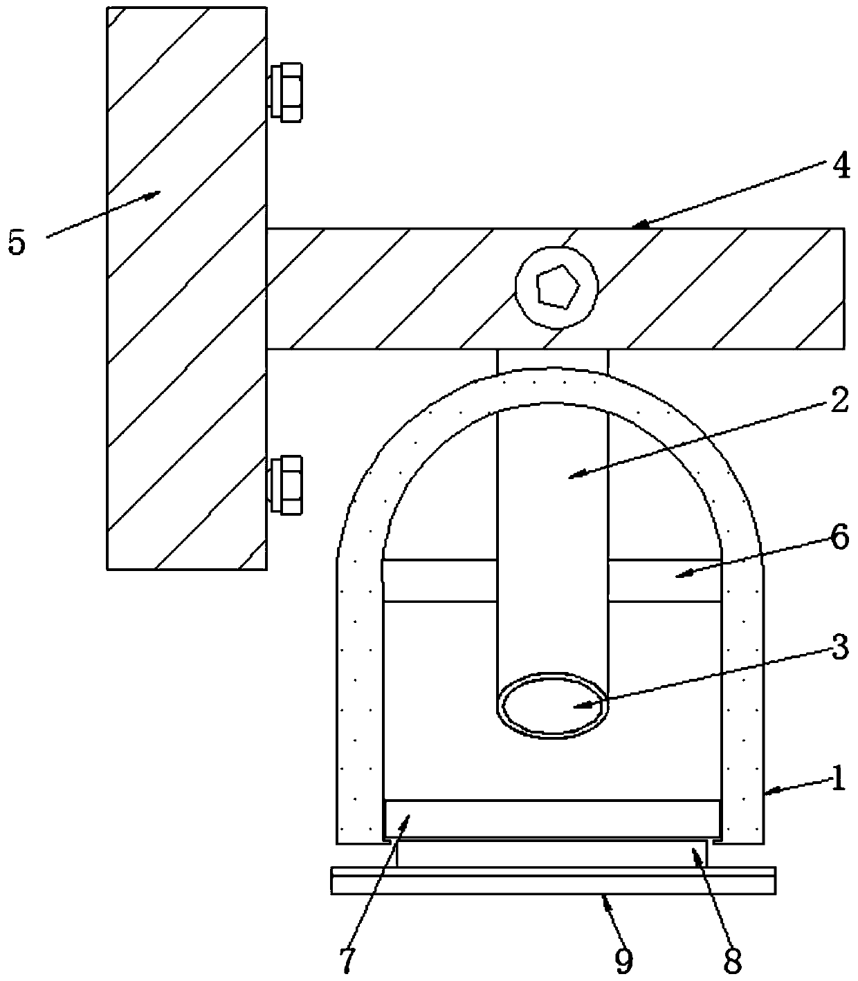
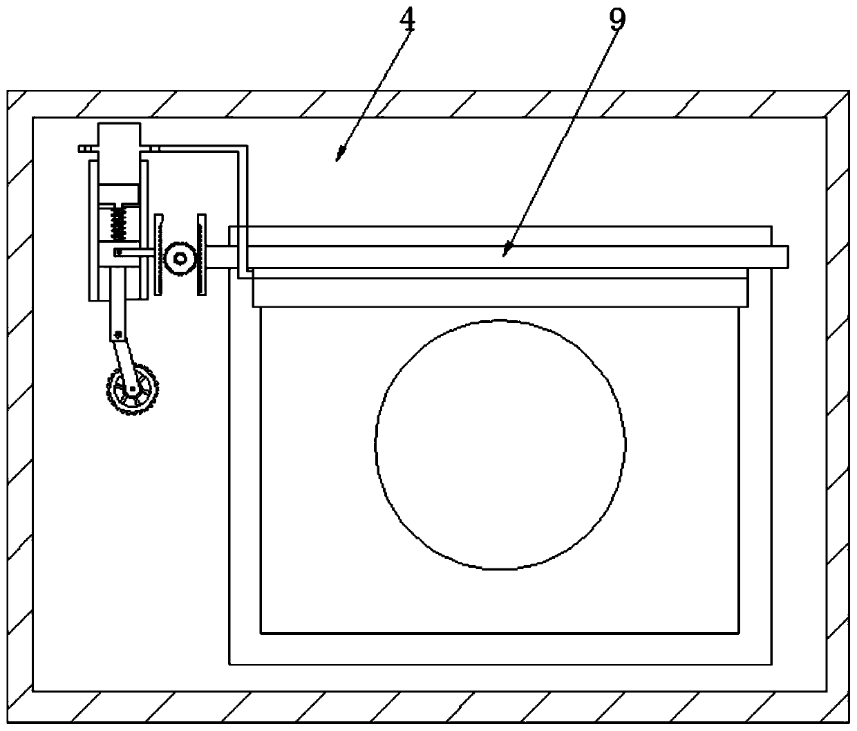
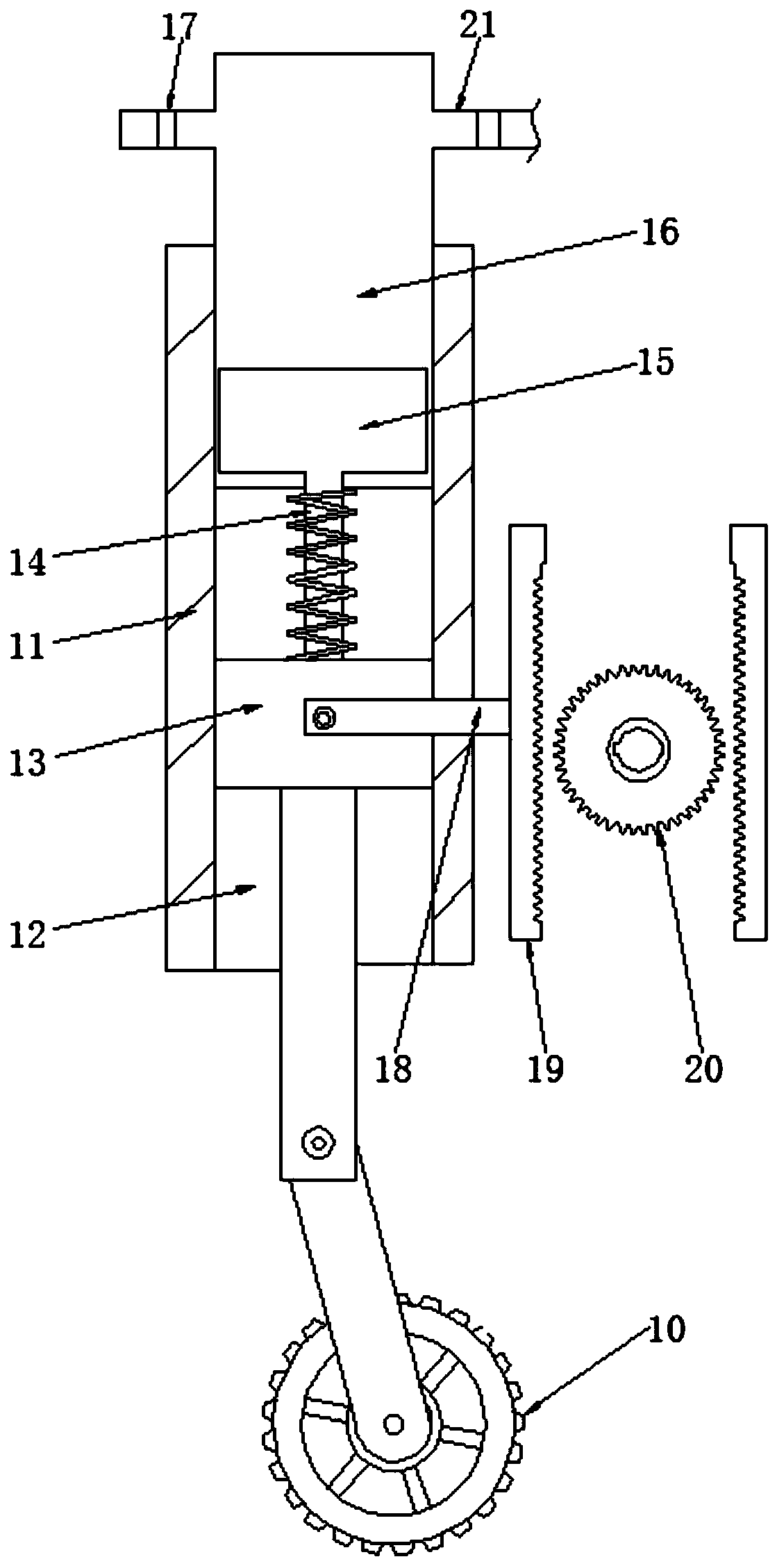
[0021] see Figure 1-3 , a monitoring camera dust removal device, comprising a dust cover 1, the inside of the dust cover 1 is fixedly connected with a connecting column 2, the bottom of the connecting column 2 is movably connected with a camera 3, and the side of the connecting column 2 away from the camera 3 is fixedly connected with a The fixed plate 4 stabilizes the connecting column 2, the left side of the fixed plate 4 is fixedly connected with a wall 5,...


PUM


Abstract

The invention relates to the technical field of monitoring, and further discloses a monitoring camera dust removal device that includes a dust cover; a connecting column is fixedly connected to the interior of the dust cover; the bottom of the connecting column is movably connected with a camera; an output shaft of a motor is movably connected with a first gear; the first gear rotates, and a sliding block reciprocates up and down in a sliding groove to drive a connecting strip to reciprocate up and down; synchronous movement of racks are realized, two racks are arranged, the rack on the rightside also moves to enable a connecting plate to synchronously move; therefore, a dedusting scraper is driven to reciprocate up and down to remove dusts attached to a transparent glass; a sucker pipe is arranged above the dedusting scraper, and movably connected with a suction layer port; the sliding block moves to drive a piston to move in a cavity and when the piston moves downwards, the dust outlet is closed, the suction layer port is opened, and dust is sucked out; and similarly, when the piston moves upwards, the dust is discharged, and the situation that the dust removal effect is affected due to the fact that the dust layers on sponge is large is avoided.

Description

technical field [0001] The invention relates to the technical field of monitoring, in particular to a monitoring camera dust removal device. Background technique [0002] In the security system, monitoring is one of the most widely used systems. In public places such as large shopping malls, banks or construction sites, monitoring is generally set up for remote control. Through the observation of the monitoring room, some accidents and abnormalities that occur outside Analyze and judge the situation, prevent problems in advance, and report to the police in time when an emergency occurs, and deal with the problem in a timely manner, and the monitored screen can be recorded and saved for use as archive data, and the reason for the incident can be understood later by calling the monitoring record And the process, and under normal circumstances, the monitoring can always keep working. The monitoring cameras are installed in every corner. Long-term use will make the surface prote...

Claims


Application Information

Patent Timeline
Patent Type & Authority Applications(China)
IPC IPC(8): B08B1/00B08B15/04
CPCB08B1/007B08B1/008
Inventor 余兰兰
Owner 余兰兰
Why Eureka
Try Eureka