Supercharge Your Innovation With Domain-Expert AI Agents!

Milling machine protection device

A protection device, milling machine technology, applied in milling machine equipment, milling machine equipment details, maintenance and safety accessories, etc.

Inactive Publication Date: 2020-03-24
SUZHOU TEXIN PRECISION ELECTRONICS CO LTD
View PDF1 Cites 0 Cited by
  • Summary
  • Abstract
  • Description
  • Claims
  • Application Information

AI Technical Summary

Problems solved by technology

[0004] In the process of realizing the present invention, the inventor found that at least the following problems in the prior art have not been solved: the above-mentioned device is not easy to be disassembled, and the protective cover will affect the movement of the tool during the tool setting and reset process

Method used


Image

  • Milling machine protection device
  • Milling machine protection device

Examples


Embodiment Construction

[0018] In order to make the technical means, creative features, goals and effects achieved by the present invention easy to understand, the present invention will be further described below in conjunction with specific embodiments.

[0019] In describing the present invention, it should be understood that the terms "upper", "lower", "front", "rear", "left", "right", "top", "bottom", "inner", " The orientation or positional relationship indicated by "outside", etc. is based on the orientation or positional relationship shown in the drawings, and is only for the convenience of describing the present invention and simplifying the description, rather than indicating or implying that the referred device or element must have a specific orientation, so as to Specific orientation configurations and operations, therefore, are not to be construed as limitations on the invention.

[0020] In the description of the present invention, it should be noted that, unless otherwise specified and...


PUM


Abstract

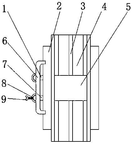
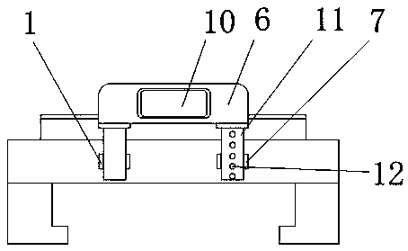
The invention discloses a milling machine protection device. The device comprises a milling machine base, wherein a sliding rail block is fixedly mounted at the top of the milling machine base, threesliding grooves are formed in the surface of the sliding rail block, a workbench is mounted on the sliding rail block in a sliding mode, a first sliding cylinder and a second sliding cylinder are fixedly mounted on the outer side of the milling machine base, an inner threaded hole is formed in the middle of the second sliding cylinder, a threaded shank is mounted in the inner threaded hole in a threaded mode, sliding rods are slidably mounted on the first sliding cylinder and the second sliding cylinder, and a plurality of limiting holes are vertically formed in the outer surfaces of the sliding rods slidably mounted on the second sliding cylinder. According to the device, when a milling machine is reset, the limiting on the sliding rods is released by rotating the threaded shank, a protective cover can be disassembled, the reset work of a milling machine tool is not affected, after the reset is completed, the protective cover is installed so as to protect operators on the front side of the workbench from being damaged by scrap iron, and through the structure which is easy to disassemble, the protective cover is flexibly disassembled, and some positioning and resetting work of themilling machine is not affected.

Description

technical field [0001] The invention relates to the technical field of milling machine protection, in particular to a milling machine protection device. Background technique [0002] At present, the milling cutter of the milling machine is the high-speed rotating part of the milling machine. The broken milling cutter and the splash of iron filings and coolant generated during the metal milling operation will cause harm to the operator. Therefore, it is necessary to add protective devices to the working part of the milling machine. Yes, the temperature of the iron filings that have just been cut and splashed out is very high. If it splashes on the fragile parts such as the operator's eyes, it will cause great harm to the human body. [0003] The existing patent (notification number: CN201220365) is a protective device for milling machines, which is composed of a lifting adjustment device and a protective cover device connected to its lower end to form a circle. One side of t...

Claims


Application Information

Patent Timeline
IPC IPC(8): B23C9/00B23Q11/08
CPCB23C9/00B23Q11/08
Inventor 方国章
Owner SUZHOU TEXIN PRECISION ELECTRONICS CO LTD
Features
  • R&D
  • Intellectual Property
  • Life Sciences
  • Materials
  • Tech Scout
  • Unparalleled Data Quality
  • Higher Quality Content
  • 60% Fewer Hallucinations
Learn More