Etching device for producing machine part

A technology for mechanical parts and engraving, which is applied in the field of engraving devices for the production of mechanical parts. It can solve problems such as inability to buffer, high initial force of engraving, and damage to the edge of the engraving knife, so as to facilitate installation and disassembly and improve the overall connection strength. Effect

Inactive Publication Date: 2020-03-24
ZHUZHOU HUAXIN PRECISION IND
View PDF5 Cites 1 Cited by
  • Summary
  • Abstract
  • Description
  • Claims
  • Application Information

AI Technical Summary

Problems solved by technology

[0003] In the production process of mechanical parts, some flat parts surfaces need to be engraved, but the existing engraving devices have

Method used


Image

  • Etching device for producing machine part
  • Etching device for producing machine part
  • Etching device for producing machine part

Examples


Embodiment 1

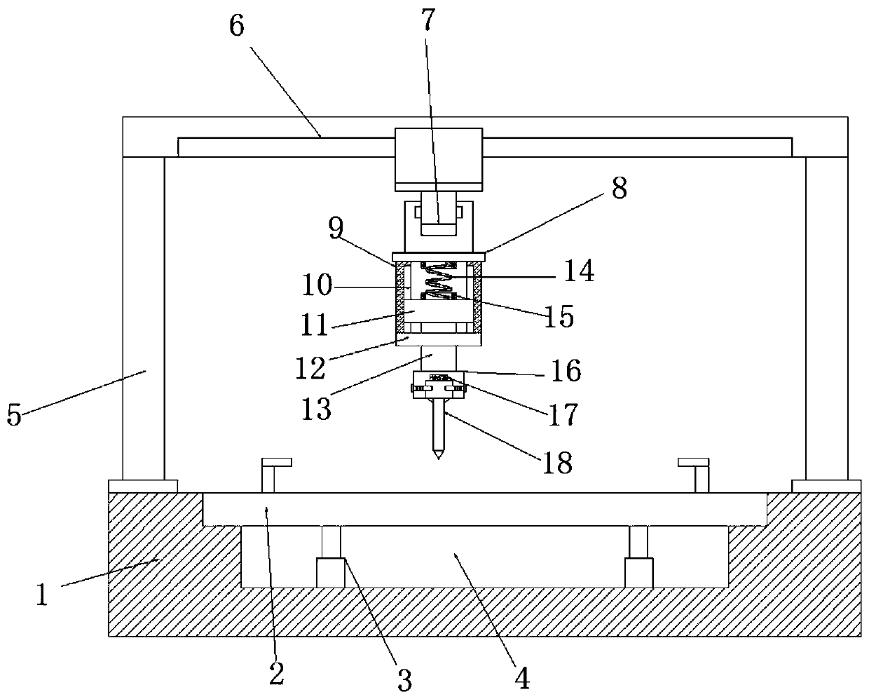
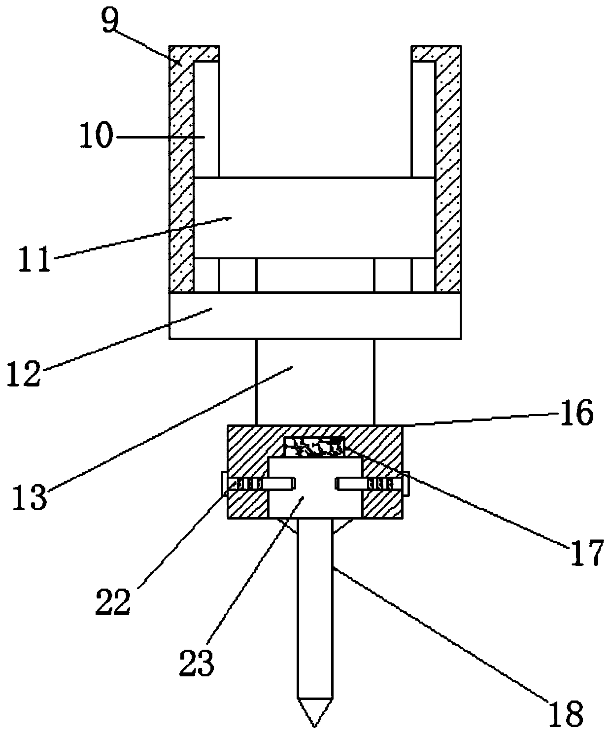
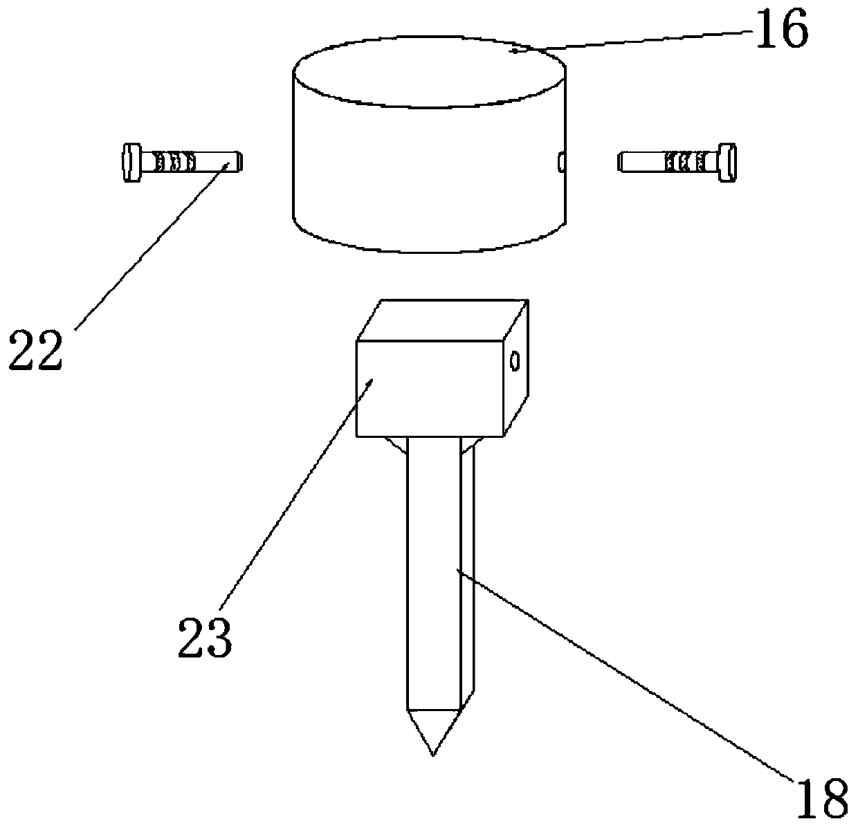
[0026] refer to Figure 1-3 , an engraving device for mechanical parts production, comprising a base 1, an installation cavity 4 is opened on the top of the base 1, and a storage mechanism is fixed on the installation cavity 4, support rods 5 are fixed on both sides of the top outer wall of the base 1, and The tops of the two support rods 5 are fixed with a drive mechanism, the bottom of the drive mechanism is fixed with a connecting plate 8, the two sides of the outer wall of the bottom of the connecting plate 8 are fixed with guide plates 9, and the bottom ends of the two guide plates 9 are fixed with the same base plate 12. A guide rod 13 is movably inserted, and the guide rod 13 is fixed with a slide block 11. One side of the two guide plates 9 is provided with a guide groove 10 that forms a sliding fit with the slide block 11. The top of the slide block 11 and the bottom of the connecting plate 8 are all fixed and limited The same spring 14 is fixed between the position r...

Embodiment 2

[0030] refer to Figure 4 , an engraving device for mechanical parts production. The difference between this embodiment and Embodiment 1 is that two screw rods 20 are threadedly inserted on the bottom plate 12, and the top of the screw rods 20 is fixed with an extrusion block 19 that contacts the outer wall of the bottom of the slider 11. , The bottom end of the screw rod 20 is fixed with a rotating block 21 .

[0031] The working principle of this embodiment: when the staff rotates the rotating block 21, the screw rod 20 moves upward, drives the extrusion block 19 to move upward, and then pushes the slider 11 to move upward, reduces the distance between the slider 11 and the connecting plate 8, and adjusts the spring The initial compression of 14 makes the adjustment of the initial extrusion force when the engraving knife 18 carries out the engraving work.


PUM


Abstract

The invention discloses an etching device for producing a machine part. The etching device comprises a drill frame, wherein a mounting cavity is formed in the top of the drill frame; a storing mechanism is fixed on the mounting cavity; support rods are fixed on the two sides of the outer walls of the top of the drill frame; a driving mechanism is fixed at the top ends of the two support rods; a connecting plate is fixed at the bottom of the driving mechanism; guiding plates are fixed on the two sides of the outer walls of the bottom of the connecting plate; the same bottom plate is fixed at the bottom ends of the two guiding plates; a guiding rod is movably connected onto the bottom plate in an inserting manner and is fixed with a sliding block; a guiding groove in sliding fit with the sliding block is formed in one sides of the two guiding plates; two limiting rings are fixed at the top of the sliding block and the bottom of the connecting plate; the same spring is fixed between the two limiting rings; a mounting block is fixed at the bottom end of the guiding rod; and an etching mechanism is fixed in the mounting block. The etching device can buffer the force intensity in initialcontact with the surface of an accessory from a nicking tool to play a protective role.

Description

technical field [0001] The invention relates to the technical field of mechanical parts production equipment, in particular to an engraving device for the production of mechanical parts. Background technique [0002] Mechanical parts, also known as mechanical components, are inseparable individual parts that make up machinery and machines. It is the basic unit of machinery. In machining, mechanical accessories are parts or components of assembled machinery. For mechanical accessories, the main points are As standard accessories and optional accessories, some mechanical accessories can enhance product functions and improve product performance. [0003] In the production process of mechanical parts, some flat parts surfaces need to be engraved, but the existing engraving devices have some deficiencies during use. The initial force of the engraving is too large, which makes the edge of the engraving knife prone to damage. Contents of the invention [0004] The purpose of th...

Claims


Application Information

Patent Timeline
IPC IPC(8): B23D79/00
CPCB23D79/00
Inventor 李辉
Owner ZHUZHOU HUAXIN PRECISION IND
Why Eureka
Try Eureka