Eureka AIR delivers breakthrough ideas for toughest innovation challenges, trusted by R&D personnel around the world.

Connecting and positioning adjusting mechanism for shaping upper floating plate and lower floating plate

A positioning adjustment, floating plate technology, applied in the direction of presses, manufacturing tools, etc., can solve the problems of dirty, excessive waste powder, reduce environmental cleaning efficiency, etc., to prevent falling apart, prevent corrosion of parts from damage, enhance cleaning efficiency and The effect of protection efficiency

Active Publication Date: 2020-03-24
佛山市常捷粉末冶金科技有限公司
View PDF8 Cites 0 Cited by
  • Summary
  • Abstract
  • Description
  • Claims
  • Application Information

AI Technical Summary

Problems solved by technology

[0004] The purpose of the present invention is to solve the problem that the existing plastic machine does not have a positioning adjustment function when it is in a working state, so that the device cannot accurately perform the function of connecting and positioning when it is working, so as to prevent the device from shifting and detaching. The shaping machine does not have an auxiliary sealing mechanism during the connection operation, which will easily lead to excessive waste powder and dirt inside the device due to the long service life, which will directly affect the normal use of the device and reduce the environmental protection and cleaning of the device when it is in working condition. Due to the shortcomings of efficiency, a connection and positioning adjustment mechanism for shaping the upper and lower floating plates is proposed

Method used

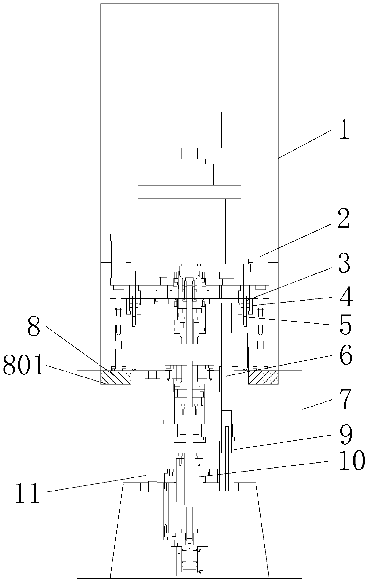
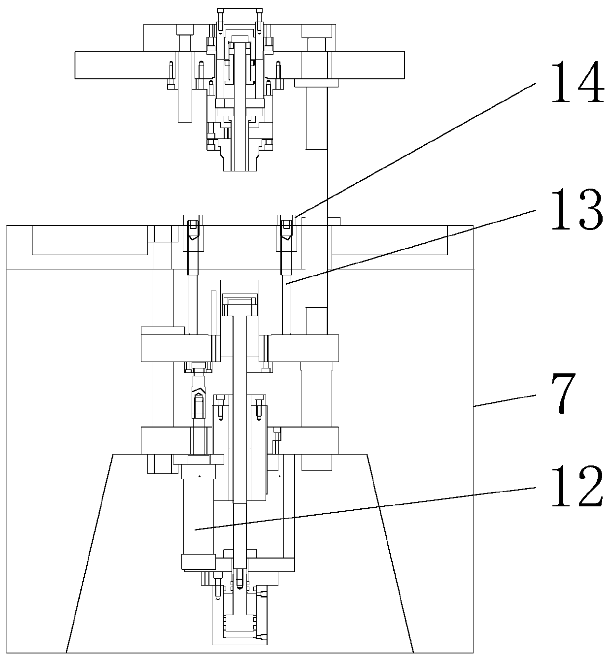
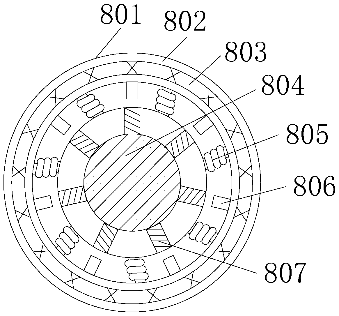

Image

  • Connecting and positioning adjusting mechanism for shaping upper floating plate and lower floating plate
  • Connecting and positioning adjusting mechanism for shaping upper floating plate and lower floating plate
  • Connecting and positioning adjusting mechanism for shaping upper floating plate and lower floating plate

Examples


Embodiment Construction

[0021] The following will clearly and completely describe the technical solutions in the embodiments of the present invention with reference to the accompanying drawings in the embodiments of the present invention. Obviously, the described embodiments are only some, not all, embodiments of the present invention. Based on the embodiments of the present invention, all other embodiments obtained by persons of ordinary skill in the art without creative efforts fall within the protection scope of the present invention.

[0022] refer to Figure 1-3 , a connection and positioning adjustment mechanism for shaping the upper and lower floating plates, including an upper floating plate 1, an upper cylinder 2 is installed inside the upper floating plate 1, through the air pressure connection between the upper cylinder 2 and the lower cylinder 12, the upper floating plate can be facilitated 1 The impact force of the connection operation with the lower floating plate 7 is weakened, so that...


PUM


Abstract

The invention discloses a connecting and positioning adjusting mechanism for shaping an upper floating plate and a lower floating plate, and relates to the technical field of shaping of upper and lower floating plates. The connecting and positioning adjusting mechanism comprises an upper floating plate. An upper cylinder is mounted in the upper floating plate; and the upper floating plate is internally connected with an upper core rod demolding adjusting assembly; the outer side of the upper core rod demolding adjusting assembly is connected with an upper tightening nut; the bottom of the upper core rod demolding adjusting assembly is provided with an upper limiting adjusting assembly; the upper floating plate is internally provided with a lower floating plate; and the lower floating plateis internally connected with a guide rod. In the present invention, the device can achieve a sealing clamping function under the auxiliary sealing effect of auxiliary mechanism when the two floatingplates are clamped and connected, so that the situation that when the device is in the working state, dust and impurities in the external environment enter the device, and consequently damage, blockage and faults are caused is prevented, and the cleaning efficiency and the protection efficiency of the device in the working state are improved.

Description

technical field [0001] The invention relates to the technical field of shaping upper and lower floating plates, in particular to a connection and positioning adjustment mechanism for shaping upper and lower floating plates. Background technique [0002] With the development of science and technology and the progress of the times, the craft industry has gradually paid attention to it. According to the production process of powder pressed products, powder products need to be sintered and shaped before they can be used. The shaping machine is a machine that integrates crushing and shaping and single-function shaping. Different stone materials and different uses can be achieved by changing the feeding method and core structure of the crushing chamber. On the basis of ensuring that the particle shape of the crushed stone meets the standard, the output can be greatly increased, and the premise of not needing to expand equipment investment Under this condition, the functions of one...

Claims


Application Information

Patent Timeline
Patent Type & Authority Applications(China)
IPC IPC(8): B30B15/00
CPCB30B15/00
Inventor 李习诚陈扬李明
Owner 佛山市常捷粉末冶金科技有限公司
Why Eureka
Eureka Blog
Learn More