Lockable rotary driving mechanism, electric rotary seat and automobile

A rotary drive mechanism and locking technology, applied in the direction of movable seats, vehicle seats, vehicle parts, etc., can solve the problems affecting seat comfort, hidden dangers, insufficient locking torque of electric rotating seats, etc. Effects of insufficient locking torque and large locking torque

Active Publication Date: 2020-03-24
诺创汽车科技(上海)有限公司
View PDF8 Cites 1 Cited by
  • Summary
  • Abstract
  • Description
  • Claims
  • Application Information

AI Technical Summary

Problems solved by technology

[0003] In the existing gear transmission structure, there are more or less gaps in the meshing between the gears, but for the electric rotating seat using gear transmission, due to the increase of the force arm, the gear meshing gap will often be reduced in the direction of seat rotation. Zoom in, and eventually cause the seat to shake in the direction of rotation, which not only affects the comfort of the seat, but also easily brings safety hazards
In addition, the existing electric seats are generally driven by a DC motor, and the locking torque of the DC motor is generally 120Nm. Even with a triple reduction ratio, the locking torque that can be provided is only 360Nm. The thousand-level Nm torque of car seats is very different, so there is a risk of insufficient locking torque for electric swivel seats

Method used


Image

  • Lockable rotary driving mechanism, electric rotary seat and automobile
  • Lockable rotary driving mechanism, electric rotary seat and automobile
  • Lockable rotary driving mechanism, electric rotary seat and automobile

Examples


Embodiment 1

[0044] This embodiment relates to a lockable rotary drive mechanism, which can be used on a car seat to realize the electric rotary adjustment of the seat, and at the same time, the locking torque after the seat adjustment can be improved through the rotary drive mechanism , to ensure the stability of the seat.

[0045] It should be noted that this embodiment specifically uses a car seat as an example to describe the structure and use of the rotary drive mechanism. It can be used in seats on other occasions to also realize the rotatable adjustment of the seat and provide better locking torque.

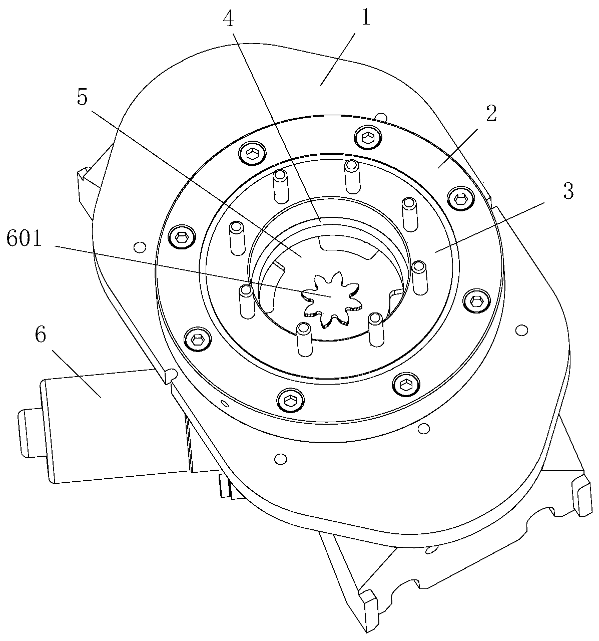
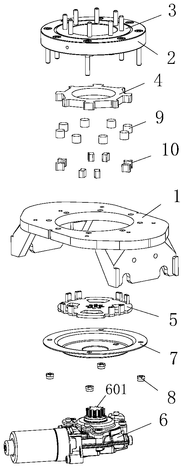
[0046] In overall design, the figure 1 and combine figure 2 As shown in , the lockable rotary drive mechanism of this embodiment includes a fixed bracket 1, a rotary bearing plate, a locking plate 4, a rotary drive module, a shift fork 5, a rigid sealing body 9 and an elastic reset member 10 .

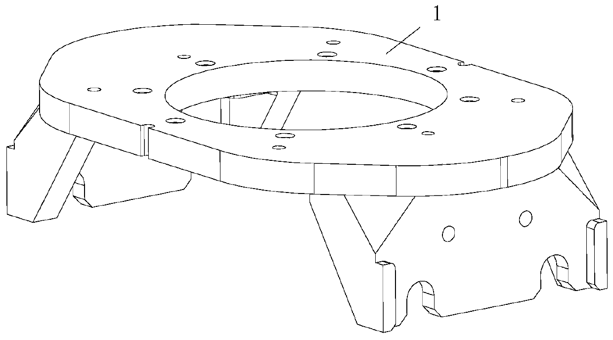
[0047] Wherein, the fixed bracket 1 of this embodiment constitutes the load-bearing ba...

Embodiment 2

[0066] This embodiment relates to an electric swivel seat, which includes a seat body with a seat frame, and a lockable rotary drive mechanism as in Embodiment 1, and the above-mentioned seat frame and the rotary drive mechanism Circle 3 is fixedly connected.

[0067] Simultaneously, this embodiment also relates to a kind of automobile, promptly is equipped with above electric rotating seat on this automobile.

[0068] The automobile and the electric rotating seat of this embodiment, by applying the rotating drive mechanism in Embodiment 1, not only can realize the electric rotating adjustment of the seat, but also can provide a larger locking torque, which can overcome the locking torque in the prior art. It has the disadvantage of small stop torque, but has good practicability.


PUM


Abstract

The invention provides a lockable rotary driving mechanism, an electric rotary seat and an automobile. The rotary driving mechanism comprises a fixed support, a rotary bearing disc which is fixedly connected with the fixed support and provided with an inner ring, a locking disc which is fixedly connected with the inner ring and provided with a plurality of protruding blocks, wedge-shaped spaces defined by the locking disc and the fixed support jointly are formed between the adjacent protruding blocks, and rigid gap sealing bodies and elastic reset pieces are arranged in the wedge-shaped spaces. The rotary driving mechanism further comprises a rotary driving module fixedly connected with the fixing support and a shifting fork connected to the power output end of the rotary driving module. The rotary driving mechanism has a locking function, can provide large locking torque, and can overcome the defect of insufficient locking torque in the prior art.

Description

technical field [0001] The present invention relates to the technical field of electric swivel seats, in particular to a lockable rotary drive mechanism that can be used to drive the seat to rotate. Cars with this seat. Background technique [0002] In order to improve the convenience of car seats, electric swivel seats have become the research and development direction of some car companies. At present, in the concept electric swivel seats, the motor drives the seat frame to rotate through the gear and ring gear structure. The rotatable adjustment of the seat is realized, and the locking feature of the worm-worm mechanism inside the motor is also used in the rotating direction of the seat, so as to indirectly realize the locking of the seat. [0003] In the existing gear transmission structure, there are more or less gaps in the meshing between the gears, but for the electric rotating seat using gear transmission, due to the increase of the force arm, the gear meshing gap ...

Claims


Application Information

Patent Timeline
IPC IPC(8): B60N2/14
CPCB60N2/146
Inventor 周安明赵丹孙继国赵磊周俊赵国朝孟令娜
Owner 诺创汽车科技(上海)有限公司
Why Eureka
Try Eureka