
Bolt positioning type blade rotating structure and blade type pneumatic rotating index plate

A rotating structure and positioning technology, which is used in precision positioning equipment, metal processing machinery parts, metal processing equipment, etc., can solve the problems of inability to merge forward rotation and reverse rotation, high production costs, and low positioning accuracy. The effect of light weight, low cost and high positioning accuracy

Inactive Publication Date: 2021-11-12
东莞市迈阔自动化科技有限公司
View PDF0 Cites 0 Cited by
  • Summary
  • Abstract
  • Description
  • Claims
  • Application Information

AI Technical Summary

Problems solved by technology

[0003] In mechanical equipment, the driving parts commonly used for indexing and positioning include cam divider and pneumatic indexing plate, etc. These driving parts have defects such as large size, heavy weight, low positioning accuracy, small locking torque force after positioning, or locking clearance, etc., and , forward rotation and reverse rotation cannot be merged, and at the same time, the production cost is relatively high (the cam splitter requires special equipment to process the cam)

Method used


Image

  • Bolt positioning type blade rotating structure and blade type pneumatic rotating index plate
  • Bolt positioning type blade rotating structure and blade type pneumatic rotating index plate
  • Bolt positioning type blade rotating structure and blade type pneumatic rotating index plate

Examples


Embodiment Construction

[0030] The implementation of the present invention will be described in detail below in conjunction with the accompanying drawings. The accompanying drawings are only for reference and description, and do not constitute a limitation to the protection scope of the present invention.

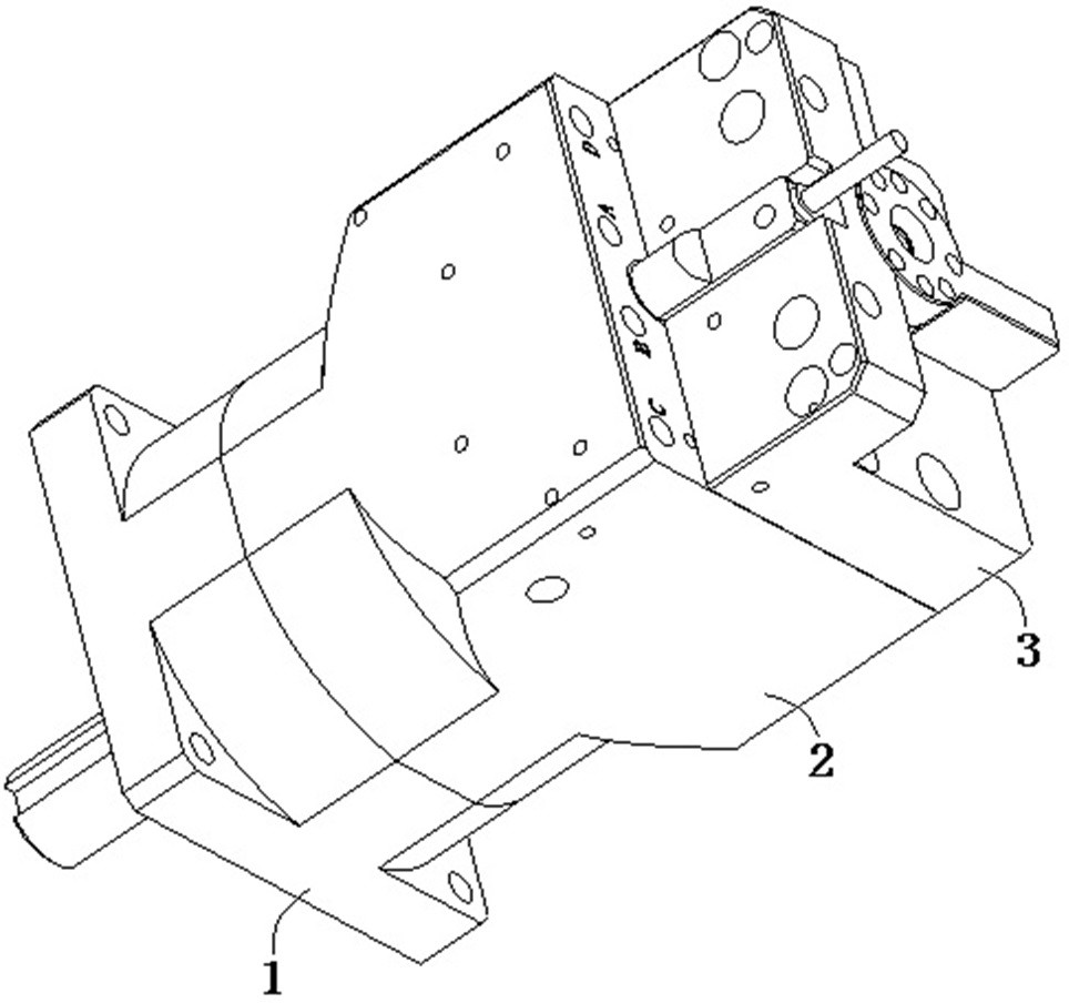
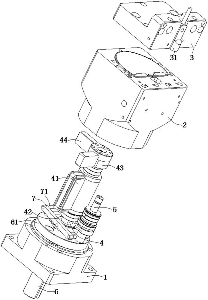
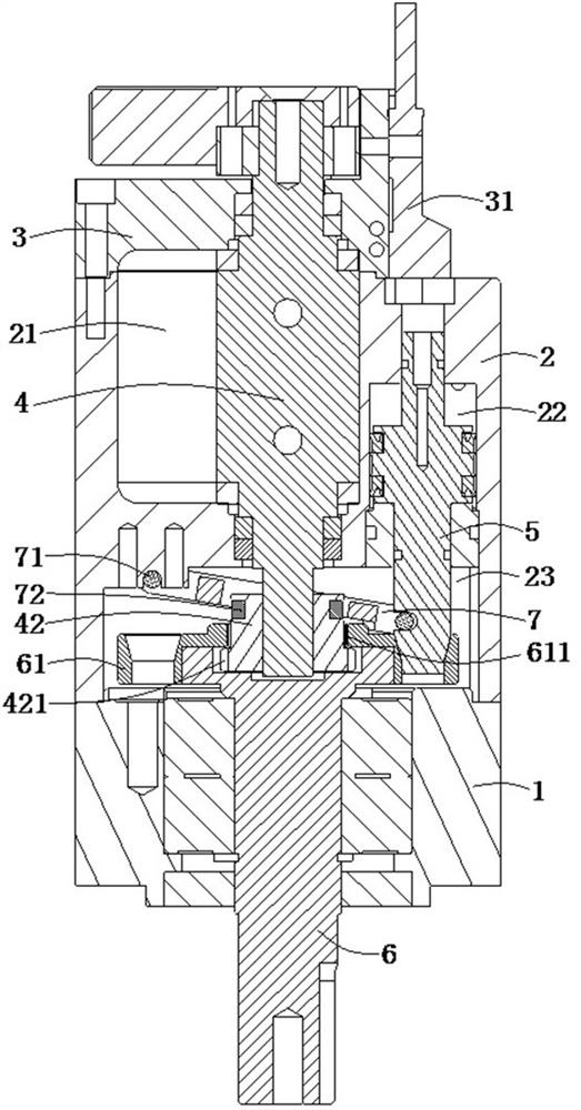
[0031] refer to Figure 1 to Figure 7 , a pin positioning type blade rotating structure, including a housing assembly, the input end of the housing assembly is provided with a blade aerodynamic chamber 21 and a bolt aerodynamic chamber 22, a blade shaft 4 is rotatably connected in the blade aerodynamic chamber 21, the blade The blade 41 of the shaft 4 is accommodated in the blade aerodynamic chamber 21, the pin aerodynamic chamber 22 is slidingly connected with the pin 5, the output end of the housing assembly is provided with an output piece and a linkage chamber 23, and the connection end of the output piece is located in the linkage chamber 23 , the end of the pin 5 extends into the linkage cav...


PUM


Abstract

The invention belongs to the technical field of control components, and particularly discloses a bolt positioning type blade rotating structure and a blade type pneumatic rotating index plate. The bolt positioning type blade rotating structure comprises a shell assembly; a blade pneumatic cavity and a bolt pneumatic cavity are arranged at an input end of the shell assembly; a blade shaft is rotatably connected into the blade pneumatic cavity; blades of the blade shaft are contained in the blade pneumatic cavity; a plug pin is slidably connected into the plug pin pneumatic cavity; an output end of the shell assembly is provided with an output piece and a linkage cavity; a connecting end of the output piece is located in the linkage cavity; a tail end of the plug pin extends into the linkage cavity and is intermittently inserted into or withdrawn from an indexing positioning hole of the output piece; and a tail end of the blade shaft extends into the linkage cavity and is rotatably connected with the output piece along with retreating of the plug pin. The blade rotating structure integrates the rotating action of the blades and the sliding positioning action of the plug pin, and has the advantages of being small in size, light in weight, large in driving and locking torque force, high in positioning precision and capable of smoothly switching forward rotation and reverse rotation.

Description

technical field [0001] The invention belongs to the technical field of control components, and in particular relates to a pin positioning type blade rotating structure and a blade type pneumatic rotating indexing plate. Background technique [0002] The indexing plate is a machine tool accessory that clamps the workpiece on the chuck or between two centers, and makes it rotate, index and position, and is mostly used in automation equipment. [0003] In mechanical equipment, the driving parts commonly used for indexing and positioning include cam divider and pneumatic indexing plate, etc. These driving parts have defects such as large size, heavy weight, low positioning accuracy, small locking torque force after positioning, or locking clearance, etc., and , forward rotation and reverse rotation cannot be merged, and at the same time, the production cost is relatively high (the cam splitter requires special equipment to process the cam). [0004] Therefore, the inventors dev...

Claims


Application Information

Patent Timeline
IPC IPC(8): B23Q16/02
CPCB23Q16/02B23Q16/021B23Q16/022
Inventor 孙武
Owner 东莞市迈阔自动化科技有限公司
Learn More