
Air supply structure and air conditioning unit

A component and air conditioning technology, applied in railway car body parts, railway vehicle heating/cooling, transportation and packaging, etc., can solve problems such as uneven air supply

Pending Publication Date: 2020-03-24
GREE ELECTRIC APPLIANCES INC
View PDF1 Cites 3 Cited by
  • Summary
  • Abstract
  • Description
  • Claims
  • Application Information

AI Technical Summary

Problems solved by technology

[0004] The embodiment of the present invention provides an air supply structure and an air conditioning unit to solve the technical problem of uneven air supply in the air supply structure in the prior art

Method used


Image

  • Air supply structure and air conditioning unit
  • Air supply structure and air conditioning unit

Examples


Embodiment Construction

[0019] In order to make the object, technical solution and advantages of the present invention clearer, the present invention will be described in further detail below in conjunction with the embodiments and accompanying drawings. Here, the exemplary embodiments and descriptions of the present invention are used to explain the present invention, but not to limit the present invention.

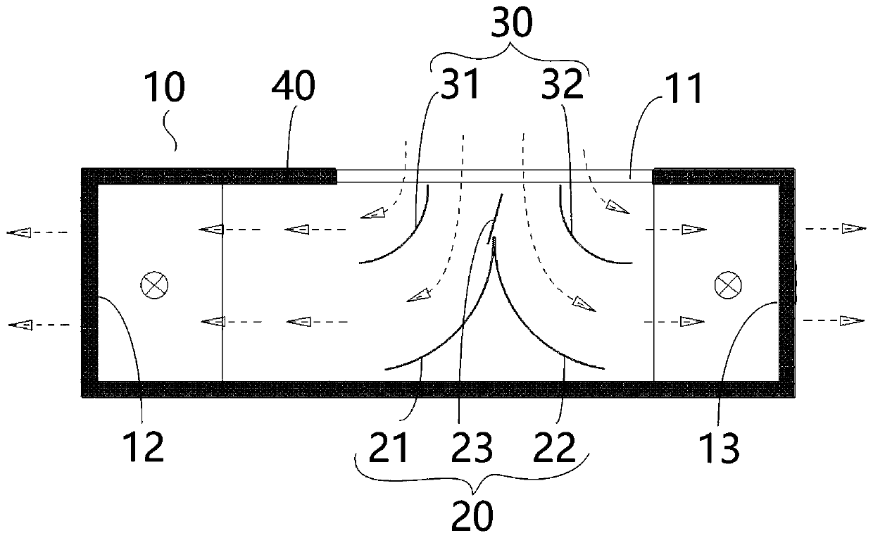
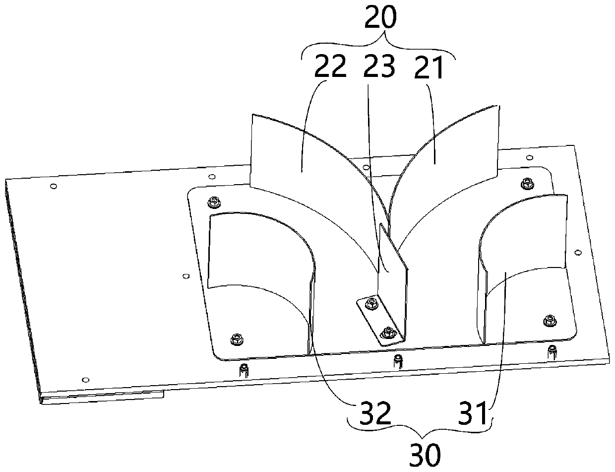
[0020] In order to solve the technical problem of uneven air supply in the air supply structure in the prior art, the present invention provides an air supply structure, such as figure 1 As shown, the air supply structure includes an air supply housing 10 , a first deflector assembly 20 and a second deflector assembly 30 . An air inlet 11 is opened in the vertical direction of the air supply housing 10 , and a first air outlet 12 and a second air outlet 13 are respectively opened on opposite sides of the air supply housing 10 in the horizontal direction. The first deflector assembly 20 is arra...


PUM


Abstract

The invention provides an air supply structure and an air conditioning unit. The air supply structure comprises an air supply shell, a first flow guide plate assembly and a second flow guide plate assembly. An air inlet is formed in the air supply shell in the vertical direction, and a first air outlet and a second air outlet are formed in the two opposite sides of the air supply shell in the horizontal direction correspondingly. The first flow guide plate assembly is arranged at the position, opposite to the air inlet and away from the air inlet, in the air supply shell. The second flow guideplate assembly is arranged at the position opposite to the air inlet and close to the air inlet, in the air supply shell. According to the technical scheme, the second flow guide plate assembly and the first flow guide plate assembly are matched, air inlet of the air inlet can be divided, airflow is divided into two layers, laminar flow is strengthened, vortexes are restrained, dynamic pressure is converted into static pressure, uniform air supply of the first air outlet and the second air outlet is achieved, flow resistance losses are reduced, and noise is lowered.

Description

technical field [0001] The invention relates to the technical field of air-conditioning equipment, in particular to an air supply structure and an air-conditioning unit. Background technique [0002] Existing rail vehicle air conditioners usually adopt the rail vehicle air conditioning air duct structure disclosed in the patent No. CN204095824U to carry out the air supply system. This structure can realize uniform air supply to a certain extent. However, soft air ducts and complex main air ducts need to be installed after the air supply outlet of the air conditioner, which has high cost, long process, large resistance, and high air supply pressure head. [0003] In addition, since the air supply outlet of the main unit of the air conditioner is connected to the main air duct of the vehicle, the main air duct is connected to the branch air duct, and the branch air duct supplies air to the passenger compartment through slits or openings. The air supply system has shortcoming...

Claims


Application Information

Patent Timeline
IPC IPC(8): B61D27/00
CPCB61D27/009
Inventor 刘加春安亚洲左小明张冠文仲优豪
Owner GREE ELECTRIC APPLIANCES INC
Learn More