
Rotary separation spring actuating device

An actuating device and a technology of rotating separation, which is applied in the docking device of aerospace vehicles, motor vehicles, transportation and packaging, etc., can solve the problems of inconsistent separation speed of the half cover, large spring force of a single spring, and difficulty in docking the half cover, etc., to achieve The effects of small attitude disturbance, large actuating distance and reliable actuation

Active Publication Date: 2020-03-24
THE GENERAL DESIGNING INST OF HUBEI SPACE TECH ACAD
View PDF7 Cites 5 Cited by
  • Summary
  • Abstract
  • Description
  • Claims
  • Application Information

AI Technical Summary

Problems solved by technology

Due to the small space on the top of the fairing, the number of actuating devices that can be arranged is limited, resulting in a large spring force of a single spring, which brings difficulties to the half-cover docking; at the same time, when the actuating device is installed on the top, the spring actuating distance is also relatively long Small, in the case of overload separation, it is not conducive to the smooth rotation of the half cover through a fixed angle, and may even cause the opened half cover to close again, and this arrangement, the position of the actuator acting on the fairing will also As the fairing rotates and changes continuously, the size of the rotating arm of the two half-covers is different, resulting in inconsistent separation speeds of the two half-covers, causing certain disturbances to the attitude of the rocket body

Method used


Image

  • Rotary separation spring actuating device
  • Rotary separation spring actuating device
  • Rotary separation spring actuating device

Examples


Embodiment Construction

[0024] The present invention will be described in further detail below in conjunction with the accompanying drawings and embodiments.

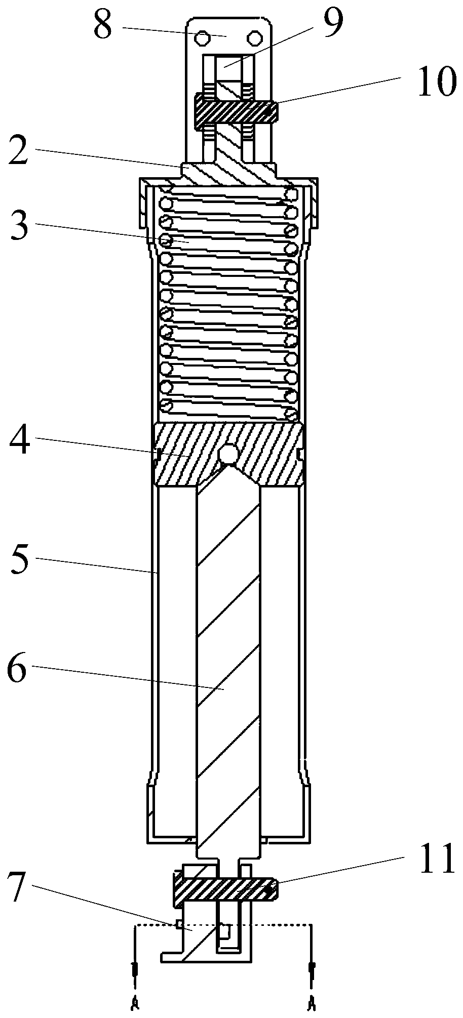
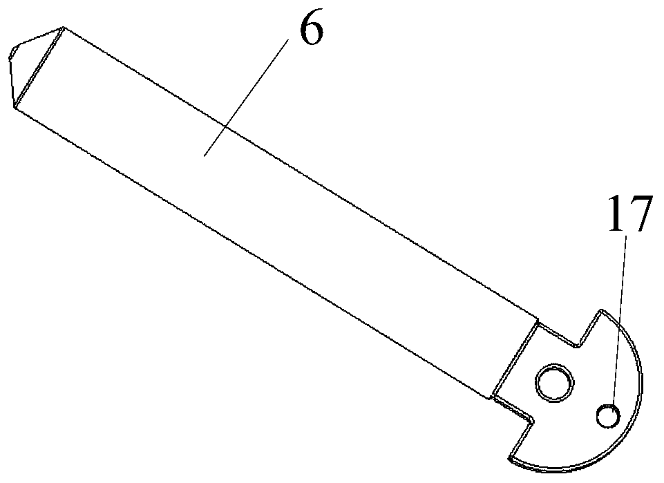
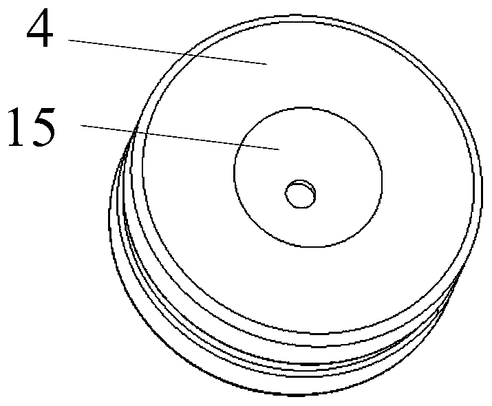
[0025] see figure 1 As shown, a rotating separation spring actuating device provided by the embodiment of the present invention includes a sleeve 5 and an operating part. The 8 upper hinges are flexibly connected, and the lower hinge 7 is arranged below the sleeve 5 . The action parts include a separation spring 3, a slider 4 and a push rod 6 located inside the sleeve 5. The upper end of the separation spring 3 is abutted against the inner top surface of the sleeve 5, and the lower end is abutted against the upper end surface of the slider 4 to Drive the slider 4 to move along the axial direction of the sleeve 5, the upper end of the push rod 6 is held against the lower end surface of the slider 4, and the lower end protrudes outward from the sleeve 5 through the opening at the lower end of the sleeve 5, and the protruding part The lower end...


PUM


Abstract

The invention discloses a rotary separation spring actuating device, which relates to the field of carrier rocket fairing separation, and comprises a sleeve and an actuating part, the lower end of thesleeve is opened, an upper hinge is arranged above the sleeve, the upper end of the sleeve is movably connected with the upper hinge, and a lower hinge is arranged below the sleeve; the action part comprises a separation spring, a sliding block and a push rod which are positioned in the sleeve; the upper end of the separation spring abuts against the inner top face of the sleeve, the lower end ofthe separation spring abuts against the upper end face of the sliding block to drive the sliding block to move in the axial direction of the sleeve, the upper end of the push rod abuts against the lower end face of the sliding block, the lower end of the push rod extends out of the sleeve through an opening in the lower end of the sleeve, and the lower end of the extending part is movably connected with the lower hinge. The rotary separation spring actuating device is simple in overall structure, large in actuation distance, capable of being arranged in the circumferential direction of the fairing in groups, reliable in actuation and small in posture disturbance.

Description

technical field [0001] The invention relates to the field of separation of launch vehicle fairings, in particular to a rotating separation spring actuating device. Background technique [0002] As a simple structure and reliable separation power device, the spring actuated device is widely used in aerospace vehicles. At the same time, since the action direction of the spring is a straight line, it is specifically used in axial separation, such as the separation of satellites and rockets, the axial separation of fairings, and the like. [0003] When the fairing is rotated and separated, the spring actuating device is often installed on the top of the fairing, and the spring compressed between the two half-covers is used to push the two half-covers to rotate and separate. Due to the small space on the top of the fairing, the number of actuating devices that can be arranged is limited, resulting in a large spring force of a single spring, which brings difficulties to the half-...

Claims


Application Information

Patent Timeline
Patent Type & Authority Applications(China)
IPC IPC(8): B64G1/64
CPCB64G1/645
Inventor 李智陈尤平肖任勤盛世龙王仰坚洪珅
Owner THE GENERAL DESIGNING INST OF HUBEI SPACE TECH ACAD
Learn More