Stiffness beam column joint concrete pouring compactness monitoring method based on endoscope

A technology of beam-column joints and concrete, which is applied in the field of concrete pouring, can solve problems such as complex structure at stiff beam-column joints, influence on structural quality, and increase the number of vibrations, so as to ensure the compactness of pouring, improve construction efficiency, and ensure construction The effect of progress

Active Publication Date: 2020-03-24
CHINA RAILWAY CONSTR ENG GROUP +1
View PDF2 Cites 0 Cited by
  • Summary
  • Abstract
  • Description
  • Claims
  • Application Information

AI Technical Summary

Problems solved by technology

It can be seen that this kind of stiff beam-column structure, especially the structure of its stiff beam-column joints is very complicated.
In actual construction, when performing beam-column concrete pouring on stiffened beam-column joints, because the steel bars at this joint are densely distributed and the operable space is small, especially the part located below the steel flange web 30 and close to the steel column 10, and the steel Between the corbel 70 and the formwork supported under the pouring steel structure 20 and close to the position of the steel column 10 (such as Figure 4 The part indicated by the middle mark 90), these parts are prone to the problem of insufficient concrete pouring density, and the concrete cannot be completely filled during the concrete pouring process. Even if exhaust and vibration measures are taken, it is often due to insufficient exhaust, vibration Insufficient pounding caused hollowing of the concrete in the beam, which greatly affected the quality of the structure
At present, there is no better way to solve the problem other than increasing the number of vibrations
However, when a problem is found after the dismantling of the formwork, it needs to be re-constructed, which has a great impact on the progress of the project, the quality of the project and the construction cost.

Method used


Image

  • Stiffness beam column joint concrete pouring compactness monitoring method based on endoscope
  • Stiffness beam column joint concrete pouring compactness monitoring method based on endoscope
  • Stiffness beam column joint concrete pouring compactness monitoring method based on endoscope

Examples


Embodiment Construction

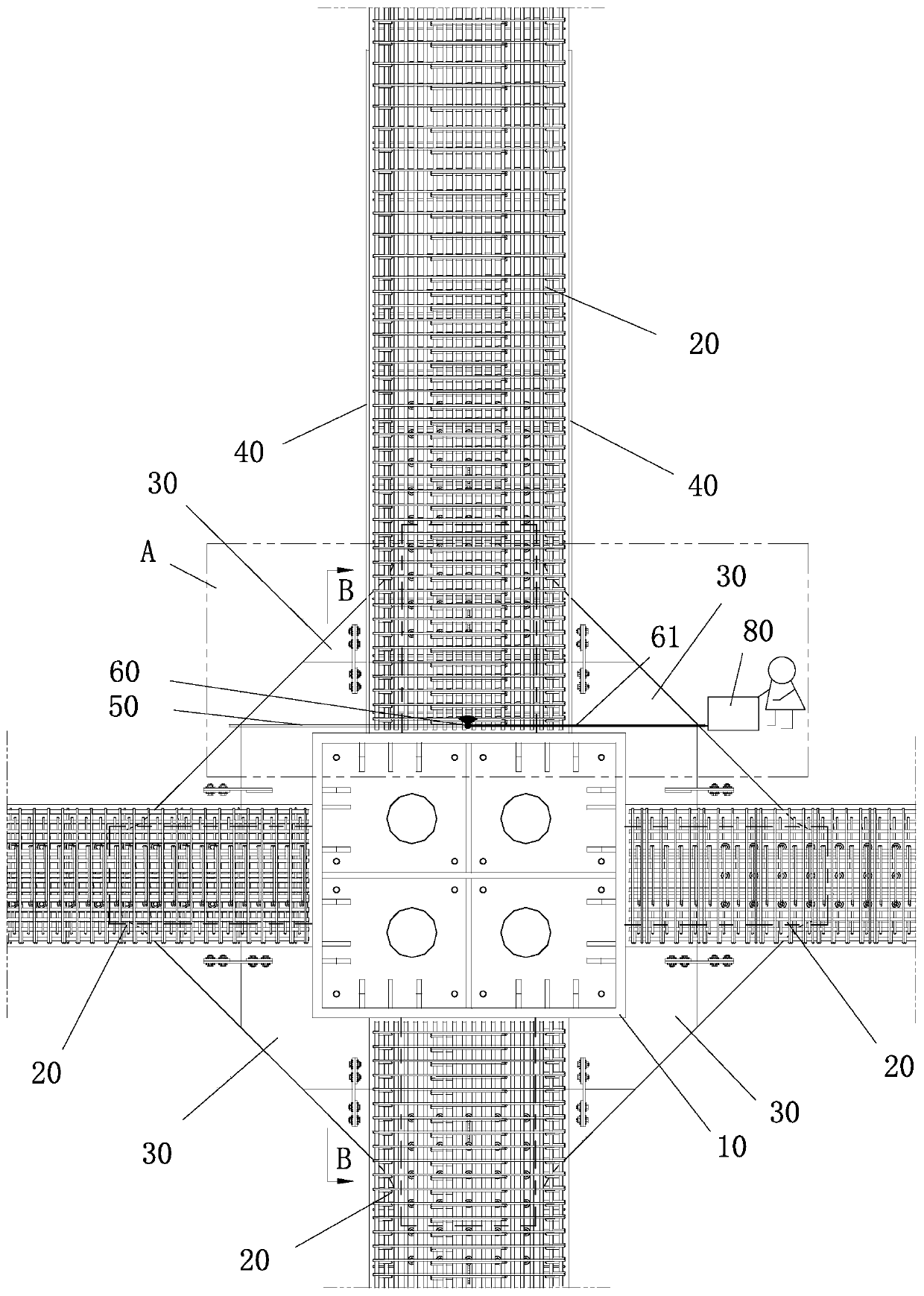
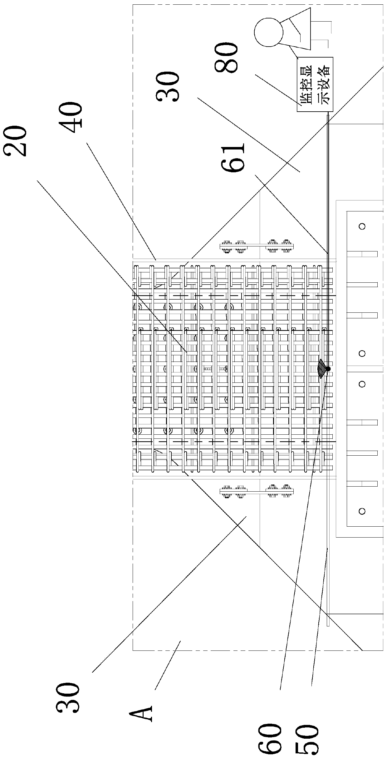
[0025] Such as Figure 1 to Figure 3 , the present invention is based on the method for monitoring the compactness of concrete pouring of stiff beam-column joints comprising the steps of endoscope:

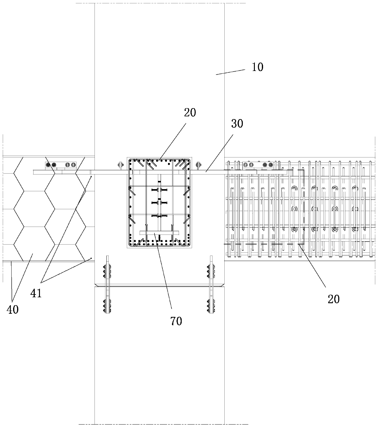
[0026] 1) After the construction of the stiff beam-column joint to be poured is completed, a formwork 40 (such as image 3 ), where wooden formwork is usually used;

[0027] 2) Use a hole opener to open holes 41 with an outer diameter of, for example, 14mm on the templates 40 on both sides, wherein: each pair of holes 41 on the templates 40 on both sides is opposite to the corresponding parts that are prone to insufficient compactness on the stiff beam-column joints, Each pair of holes 41 should be visible to the naked eye, that is, to ensure that the positions of the two holes 41 are consistent or close;

[0028] 3) Define the parts on the rigid beam-column joints that are prone to lack of compactness as observation parts, and install a transparent acrylic tube 50 on each obser...


PUM


Abstract

The invention discloses a stiffness beam column joint concrete pouring compactness monitoring method based on an endoscope. The method comprises the steps of ereting a template; forming a hole; installing a transparent acrylic pipe; connecting the endoscope with a monitoring display device through a hard cable; pushing the endoscope to a first observation point; starting to pour the beam column concrete, and performing concrete pouring compactness monitoring at each observation part from bottom to top; observing whether the concrete poured at each observation point wraps the transparent acrylic pipe or not through the monitoring display device; when the transparent acrylic pipe is wrapped, disassembling the endoscope and the transparent acrylic pipe to complete the compactness monitoring;repeating the related steps until the compactness monitoring of all observation parts is completed; and continuously pouring the beam column concrete till the stiffness beam column joint constructionis completed. The method realizes the whole-process monitoring of the hidden danger parts, is high in construction efficiency and low in construction cost, can guarantee the pouring compaction effectof the beam column concrete, and enables the construction quality to be improved.

Description

technical field [0001] The invention relates to a method for monitoring the compactness of concrete pouring of rigid beam-column joints realized based on an endoscope, and belongs to the technical field of concrete pouring. Background technique [0002] Stiff beam-column structures are widely used in high-speed railway stations because they can bear the dynamic load of trains. refer to Figure 4 , the existing stiff beam-column structure usually includes a steel column 10 with a rectangular cross-section, and steel corbels 70 are welded on each side of the steel column 10. Usually, the steel corbel 70 adopts I-steel, that is, the steel corbel 70 includes upper, The lower flange plate and the middle web connecting the upper and lower flange plates. And in order to strengthen the shear force of the steel corbel 70 and the steel column 10, the steel column 10 is connected with two adjacent steel corbels 70 through the welded steel flange web 30, usually the steel flange web 30...

Claims


Application Information

Patent Timeline
IPC IPC(8): G01N21/88G01N21/01
CPCG01N21/88G01N21/01G01N2021/8411G01N2021/0112
Inventor 董无穷
Owner CHINA RAILWAY CONSTR ENG GROUP
Why Eureka
Try Eureka