Gas relay for transformer

A technology of gas relays and transformers, applied in circuits, electric switches, electrical components, etc., can solve problems such as incomplete air intake or exhaust, fault expansion, and easy misjudgment, so as to reduce labor costs and maintenance costs, reduce The number of attendance and increase the effect of accurate judgment

Active Publication Date: 2020-03-24
WUHU JINNIU ELECTRIC
View PDF4 Cites 1 Cited by
  • Summary
  • Abstract
  • Description
  • Claims
  • Application Information

AI Technical Summary

Problems solved by technology

[0003] First, there are many different situations in the gas relay to trigger the light gas alarm. For example, the transformer oil decomposes to generate gas, which makes the open cup fall, makes the magnet contact with the light gas reed contact, and triggers the light gas signal. At the same time, the gas relay floats. The falling off of the rotating shaft, oil leakage at the joint, and incomplete air intake or exhaust in the negative pressure area are likely to cause frequent actions of light gas protection. If the operator cannot make timely and correct judgments, it may cause missed judgments for fast-growing faults and cause major accidents. disaster, and these situations are easy to paralyze people. If other faults occur, it is easy to miss a judgment, and it is impossible to accurately handle the faults that occur
[0004] Second, the existing technology judges the operation of the transformer after the action of the light gas signal, which cannot be monitored in real time, and there is a certain hysteresis. huge damage and loss

Method used


Image

  • Gas relay for transformer
  • Gas relay for transformer
  • Gas relay for transformer

Examples


Embodiment Construction

[0021] The technical solutions in the embodiments of the present invention will be clearly and completely described below in conjunction with the accompanying drawings in the embodiments of the present invention. Obviously, the described embodiments are only a part of the embodiments of the present invention, rather than all the embodiments. Based on the embodiments of the present invention, all other embodiments obtained by those of ordinary skill in the art without creative work shall fall within the protection scope of the present invention.

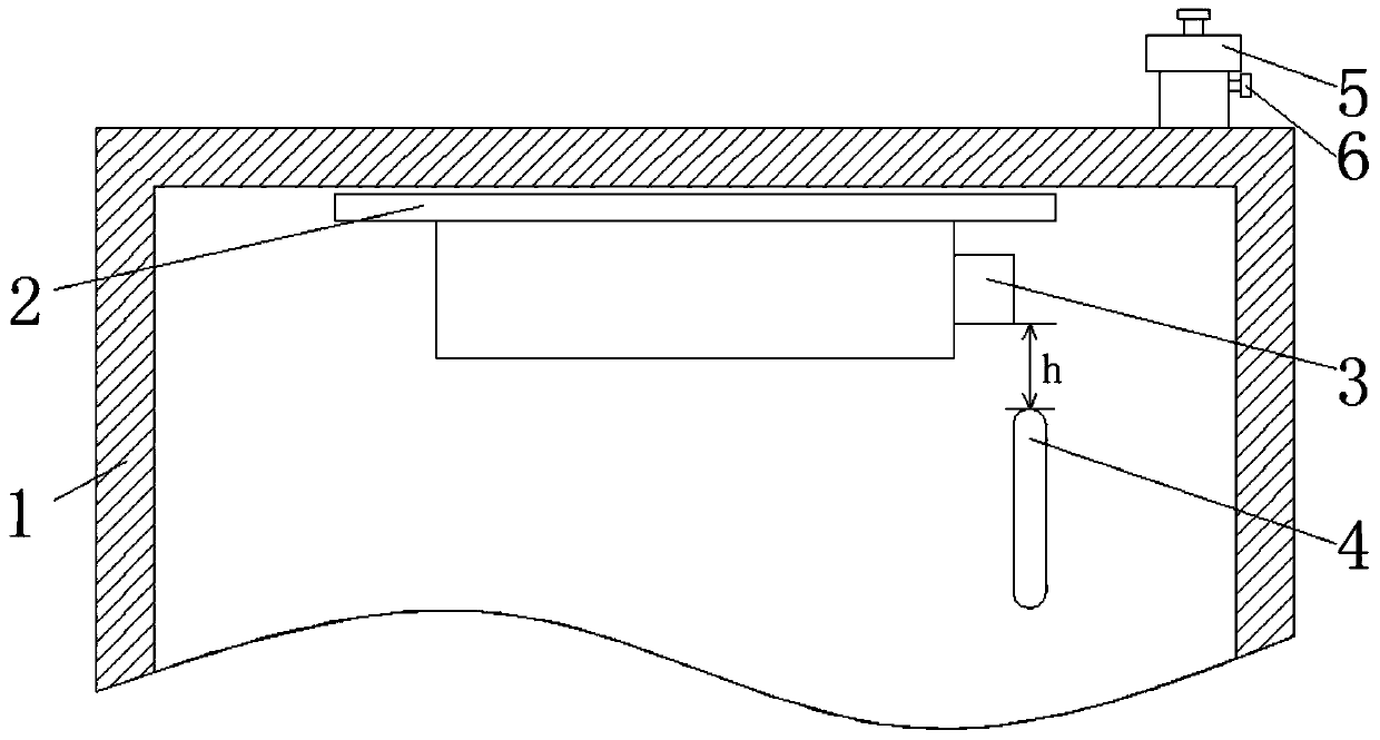
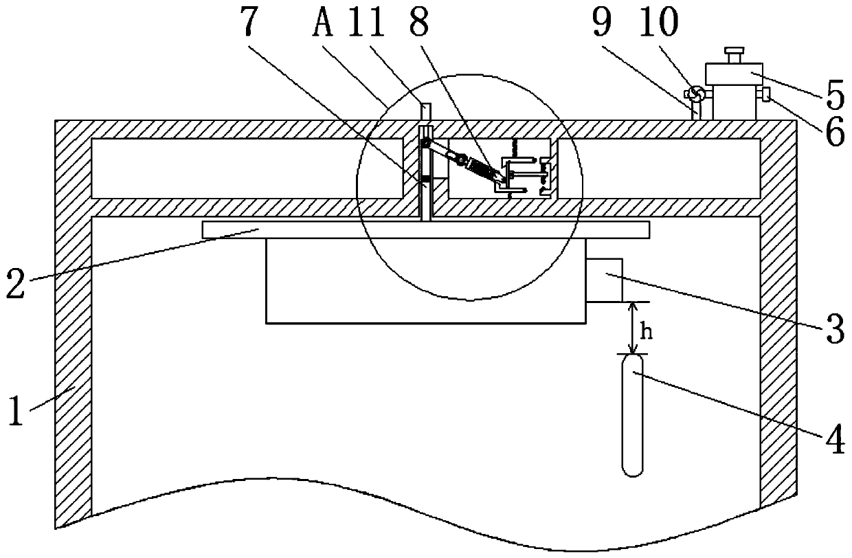
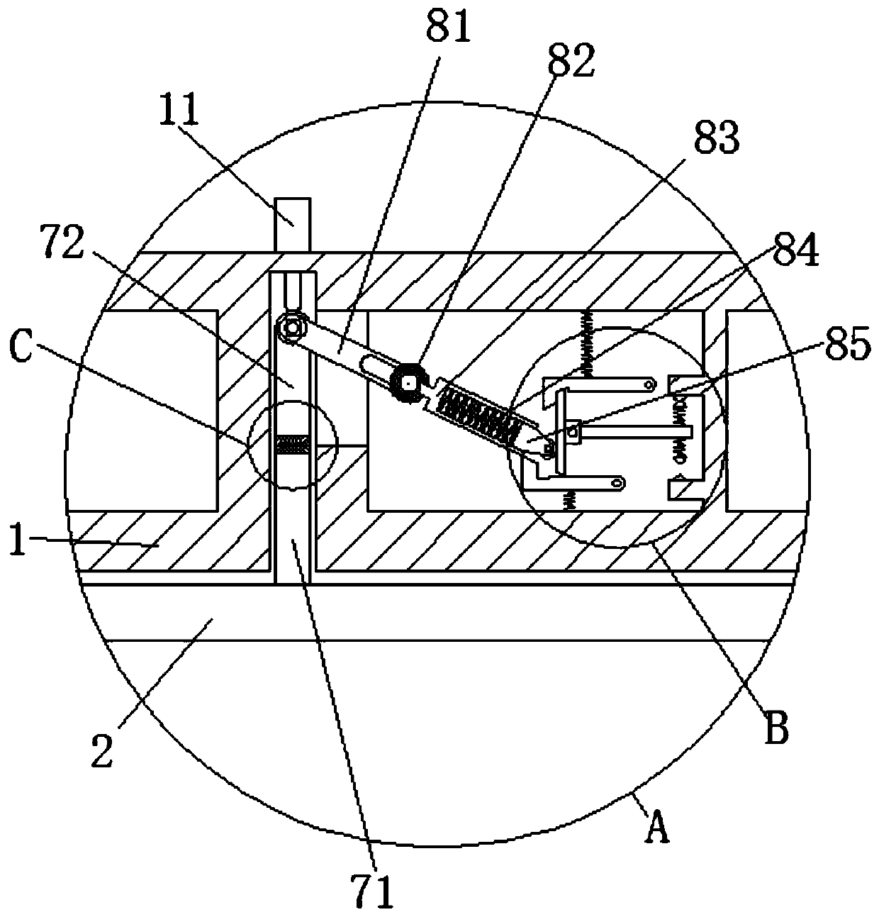
[0022] See Figure 2-6 , A gas relay for a transformer, including a housing 1, an open cup 2, a magnet 3, a light gas reed contact 4, a gas plug 5, a vent 6, a lever device 7, a roller type limit switch 8, a wire 9, a single To the air release valve 10 and the position sensor 11, the opening cup 2 is movably installed on the top of the inner cavity of the housing 1, the magnet 3 is fixedly installed on the right side of the opening cup 2...


PUM


Abstract

The invention relates to the technical field of transformer safety. The invention further discloses a gas relay for the transformer. The gas relay comprises a shell, an opening cup, a magnet, a lightgas dry reed contact, a gas plug, a gas vent, a pull rod device, a roller type travel switch, an electric wire, a one-way gas vent valve and a position sensor, the opening cup is movably installed atthe top of an inner cavity of the shell, the magnet is fixedly installed on the right side of the opening cup, and the light gas dry reed contact is movably installed in the shell and located at the position, with the distance of h, below the magnet. The pull rod device, the roller type travel switch, the electric wire and the one-way vent valve are arranged, the descending process of the openingcup is further distinguished; therefore, the gas can be automatically exhausted before the light gas signal is triggered, the oil level in the gas relay is recovered, the attendance frequency of an operator is reduced, the labor cost is reduced, the frequent triggering of the light gas signal is avoided, the accurate judgment of the operator on the condition of the transformer is increased, and the operation safety of the transformer is improved.

Description

Technical field [0001] The invention relates to the technical field of transformer safety, in particular to a gas relay for transformers. Background technique [0002] Gas relay is the most important protection device for large power transformers. When a minor fault occurs inside the transformer, such as the attached figure 1 , The gas produced by the decomposition of oil gradually accumulates on the upper part of the gas relay. When it reaches a certain amount, the opening cup is lowered by a certain distance h, and the magnet on the opening cup is attracted to the light gas reed contact to send out a light gas signal, and then it is operated The personnel open the gas plug to discharge the gas from the bleed port. When the oil level drops for some reason, the light gas protection can also be activated to send a signal. When a serious failure occurs inside the transformer, the insulating oil is quickly and largely decomposed. The pressure in the fuel tank rises sharply, and ther...

Claims


Application Information

Patent Timeline
Patent Type & Authority Applications(China)
IPC IPC(8): H01H35/26
CPCH01H35/26H01H35/2657
Inventor 劳兆伦
Owner WUHU JINNIU ELECTRIC
Why Eureka
Try Eureka