
Mobile terminal equipment

A mobile terminal and equipment technology, applied in transmission systems, antennas, antenna supports/installation devices, etc., can solve the problems of reducing antenna performance and small space, reducing antenna coupling loss, improving antenna performance, and reasonable antenna form. Effect

Pending Publication Date: 2020-03-24
SHENZHEN SUNWAY COMM
View PDF0 Cites 0 Cited by
  • Summary
  • Abstract
  • Description
  • Claims
  • Application Information

AI Technical Summary

Problems solved by technology

However, due to the small space of mobile terminal equipment (such as mobile phones, tablet computers, etc.), there is an inevitable coupling between the antenna elements, which reduces the performance of the antenna.

Method used


Image

  • Mobile terminal equipment
  • Mobile terminal equipment
  • Mobile terminal equipment

Examples


Embodiment 1

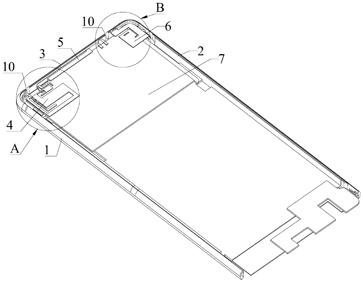
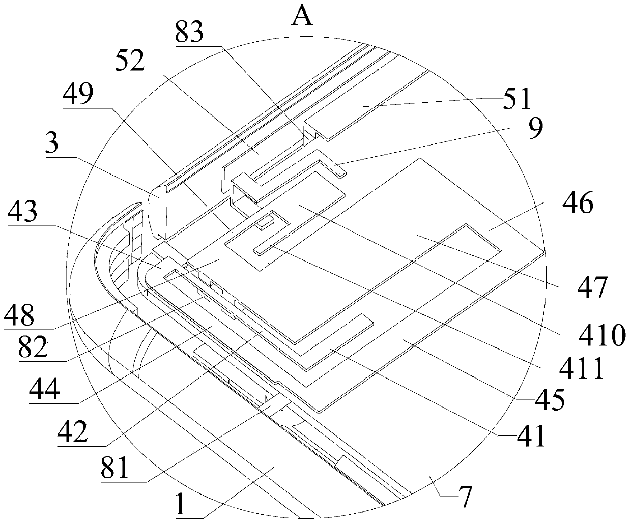
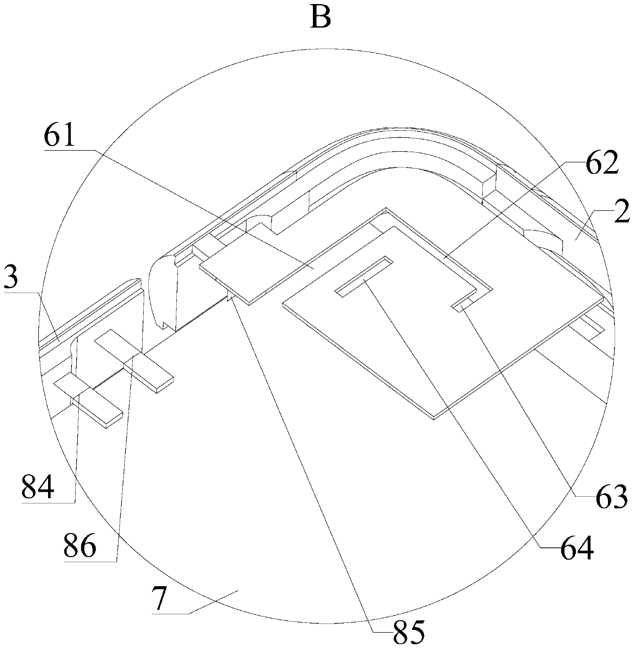
[0039] Please refer to Figure 1 to Figure 8 , Embodiment 1 of the present invention is: a mobile terminal device, including but not limited to a mobile phone and a tablet computer. Please combine Figure 1 to Figure 3 , the mobile terminal device includes a metal frame and a main control board 7 arranged in the metal frame, the metal frame is provided with a plurality of gaps 10, and the gaps 10 separate the metal frame into a left frame 1, a right frame The side frame 2 and the top frame 3 also include a first radiation sheet 4, a second radiation sheet 5 and a third radiation sheet 6, and the main control board 7 is provided with a first feeding point 81 and a second feeding point 82 , the third feed point 83, the fourth feed point 84, the fifth feed point 85 and the switch 86;

[0040] The first feeding point 81 is connected with the left frame 1 to form an IFA antenna, and the operating frequency of the IFA antenna is 2.3G-2.69Ghz; the second feeding point 82 is connect...


PUM


Abstract

The invention discloses mobile terminal equipment, which comprises a main control board, a left side frame, a right side frame and a top frame, the main control board is provided with a first feed point, a second feed point, a third feed point, a fourth feed point, a fifth feed point and a switch; the first feeding point is connected with the left side frame to form an IFA antenna; the second feeding point is connected with the first radiation sheet to form a first monopol antenna; the third feed point is connected with the second radiation sheet to form a second monopol antenna, the fourth feed point and the switch are respectively connected with the top frame to form a switchable combined antenna, and the fifth feed point is respectively connected with the third radiation sheet and the right side frame to form a loop antenna; the first monopol antenna is arranged close to the transition position of the left side frame and the top frame, the second monopol antenna is arranged close tothe top frame, and the loop antenna is arranged close to the transition position of the right side frame and the top frame. Through proper antenna layout, the mutual coupling condition of the antennas is improved, and the antenna performance is improved.

Description

technical field [0001] The present invention relates to the technical field of terminal equipment, in particular to a mobile terminal equipment. Background technique [0002] With the rapid development of communication technology, users have put forward higher requirements for the performance of mobile communication systems, and are constantly pursuing the miniaturization and portability of mobile terminal equipment. Therefore, multi-antenna systems have become the best choice for wireless communication. However, due to the small space of mobile terminal devices (such as mobile phones, tablet computers, etc.), there is an inevitable coupling effect between antenna elements, which reduces the performance of the antenna. Therefore, how to make the layout of the multi-antenna system in the mobile terminal equipment more reasonable is the key to improving the antenna performance of the mobile terminal equipment. Contents of the invention [0003] The technical problem to be s...

Claims


Application Information

Patent Timeline
IPC IPC(8): H01Q1/24H01Q1/38H01Q1/50H01Q1/52H01Q5/20H01Q5/307H01Q5/378H01Q5/50H04B7/0404
CPCH01Q1/243H01Q1/38H01Q1/50H01Q1/521H01Q5/20H01Q5/307H01Q5/378H01Q5/50H04B7/0404
Inventor 张治松
Owner SHENZHEN SUNWAY COMM
Learn More