
A Miniaturized Wide Beam Microstrip Antenna

A technology of microstrip antenna and wide beam, applied in the direction of antenna, slot antenna, resonant antenna, etc., can solve the problem that the beam width is limited within 80 degrees, the impedance bandwidth is small, etc., and achieve large wide beam performance, large impedance bandwidth, widening Effect of Beam Width

Active Publication Date: 2017-08-25
理工雷科电子(天津)有限公司
View PDF4 Cites 0 Cited by
  • Summary
  • Abstract
  • Description
  • Claims
  • Application Information

AI Technical Summary

Problems solved by technology

However, both microstrip antennas have the disadvantages of small impedance bandwidth and the beam width of the E-plane and H-plane patterns is limited to within 80 degrees.

Method used


Image

  • A Miniaturized Wide Beam Microstrip Antenna
  • A Miniaturized Wide Beam Microstrip Antenna
  • A Miniaturized Wide Beam Microstrip Antenna

Examples


Embodiment Construction

[0032] The present invention will be described in detail below with reference to the accompanying drawings and examples.

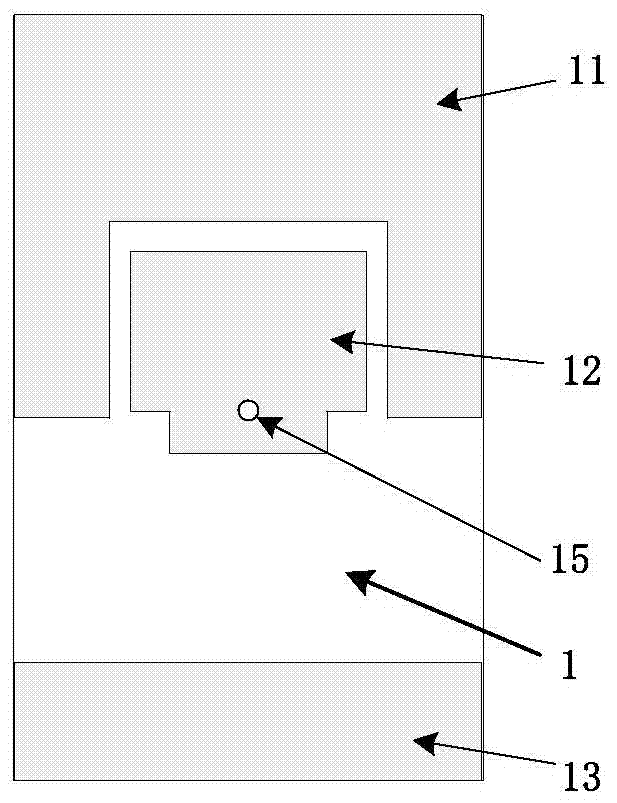
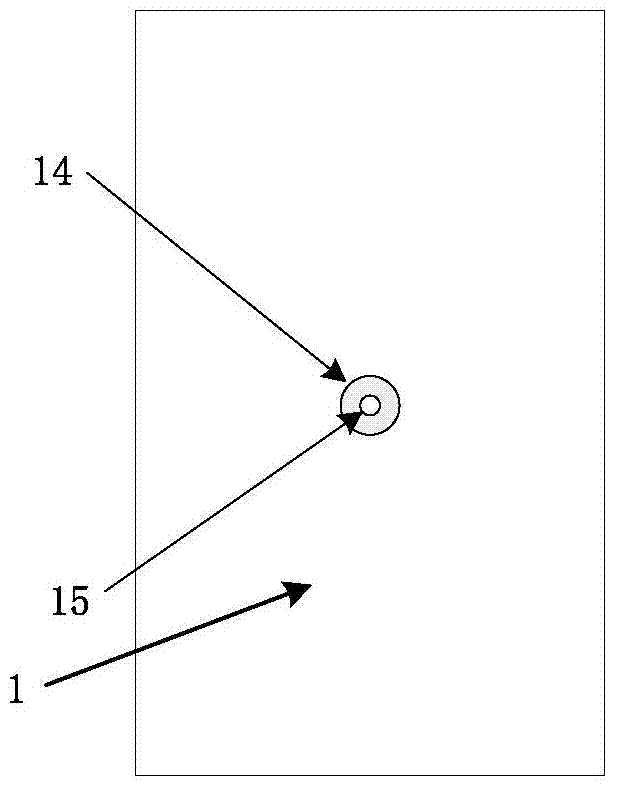
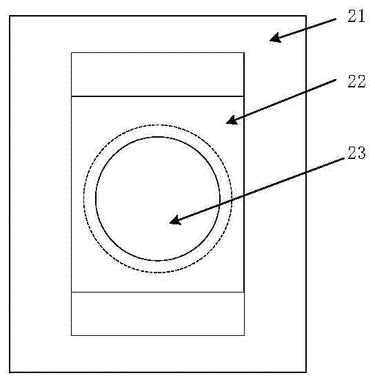
[0033] The wide-beam microstrip antenna of the present invention is mainly composed of a microstrip dielectric plate 1 and a metal base 2. The back and front patterns of the microstrip dielectric plate 1 are as shown in Figure 1, and the pattern on the back of the microstrip dielectric plate 1 is composed of a radiation patch 12, Composed of a parasitic patch 11 with a rectangular notch and a strip pad 13, the radiation patch 12 is embedded in the rectangular notch of the parasitic patch 11, and the end surface of the radiating patch 12 is flush with the rectangular notch of the parasitic patch 11 There is a protrusion on the radiating patch 12, and there is a gap between the embedded part of the radiation patch 12 and the rectangular notch; the strip-shaped pad 13 is processed on the end of the microstrip dielectric board 1 opposite to the parasitic patch ...


PUM


Abstract

The invention discloses a small wide-beam microstrip antenna. The small wide-beam microstrip antenna is that grounded U-shaped appended patches are additionally arranged about a microstrip radiation path. The small wide-beam microstrip antenna has the characteristics that the structure is simple, the size is small, and relatively large impedance bandwidth and wide beam performance can be achieved. The microstrip antenna with the structure has the advantages that the grounded U-shaped appended patches are provided, so that the capacitive resistance is introduced through a clearance between the radiation path and the U-shaped appended patches to counteract the independence component of a probe, so as to increase the bandwidth of the antenna; meanwhile, the size of the radiation path is far less than the path size of the common microstrip antenna, wherein the path size is half the free space wavelength (7.5mm), so that the size of the radiation path is reduced, and the effect of increasing the beam width of the antenna is achieved to some extent; few wave absorbing materials with proper thickness are adhered to an antenna metal base, thus the coupling of antenna arrays can be improved during arraying, and moreover, the beam width of the antenna can be increased.

Description

technical field [0001] The invention belongs to the technical field of microstrip antennas, and in particular relates to a miniaturized wide-beam microstrip antenna, which is applicable to various types of radar antennas, and is especially suitable for high-resolution synthetic aperture radar imaging and large-angle scanning phased array radar. Background technique [0002] "Large-angle scanning phased array" has always been a hot and difficult point in the field of phased array research. The expansion of modern wireless communication requirements and the development of remote sensing detection technology provide a wider application field for large-angle scanning phased arrays. The research on "phased array large-angle scanning" can be traced back to the 1960s and 1970s. At first, people turned the radar platform mechanically to obtain a larger scanning area. This method combined with mechanical rotation does not find out the factors restricting the large-angle scanning of...

Claims


Application Information

Patent Timeline
Patent Type & Authority Patents(China)
IPC IPC(8): H01Q9/04H01Q13/08H01Q13/10H01Q1/38
Inventor 于冲刘峰沈国松白冰
Owner 理工雷科电子(天津)有限公司
Learn More