A small outdoor power cabinet

A power cabinet and outdoor technology, applied in the field of power cabinets, can solve problems such as inability to save resources, weak bearing capacity of thin nails, troubles, etc., and achieve the effect of expanding the operating space

Inactive Publication Date: 2020-11-10
SUZHOU QIHUA MACHINERY & ELECTRICAL EQUIP
View PDF2 Cites 0 Cited by
  • Summary
  • Abstract
  • Description
  • Claims
  • Application Information

AI Technical Summary

Problems solved by technology

[0004] For example, the hoop device such as the application number 201821229119.6 is directly fixed on the outer wall of the electrical cabinet, but after the hoop device is installed on the outer wall of some small electrical cabinets, the following obvious defects still exist when it is installed and fixed on the trunk: The hoop is installed by embracing the tree trunk. It is very troublesome to adjust the diameter range that the hoop can hold during the installation process. In addition, many people are required to cooperate during the installation process, which wastes manpower and material resources. inability to conserve resources
[0005] In addition, if the hanging lugs are directly installed on the outside of the electrical cabinet, and the hanging lugs are directly plugged and fixed to the trunk, the trunk skin is relatively dry, so it is very hard. Nails cannot be inserted into the tree trunk well, and it is laborious. Thin nails are easier to insert, but the load-bearing capacity of thin nails is weak. Using multiple thin nails will waste resources. Moreover, using lugs and fixing them through screw insertion The method still requires the cooperation of multiple people, which is very troublesome

Method used


Image

  • A small outdoor power cabinet
  • A small outdoor power cabinet
  • A small outdoor power cabinet

Examples


Embodiment Construction

[0031] The following will clearly and completely describe the technical solutions in the embodiments of the present invention with reference to the accompanying drawings in the embodiments of the present invention. Obviously, the described embodiments are only some, not all, embodiments of the present invention. Based on the embodiments of the present invention, all other embodiments obtained by persons of ordinary skill in the art without making creative efforts belong to the protection scope of the present invention.

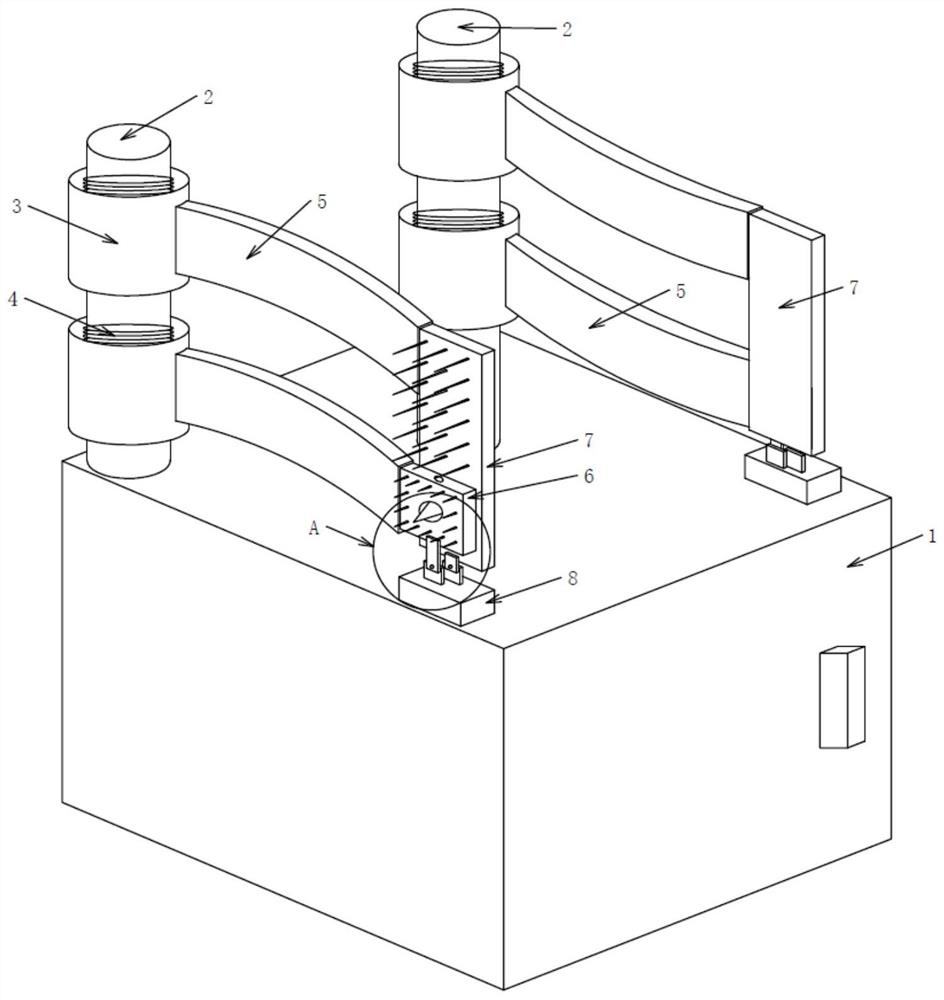
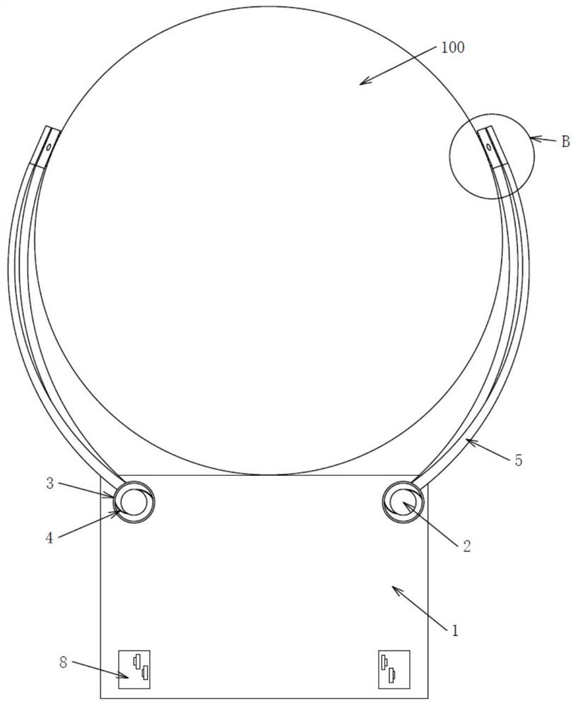
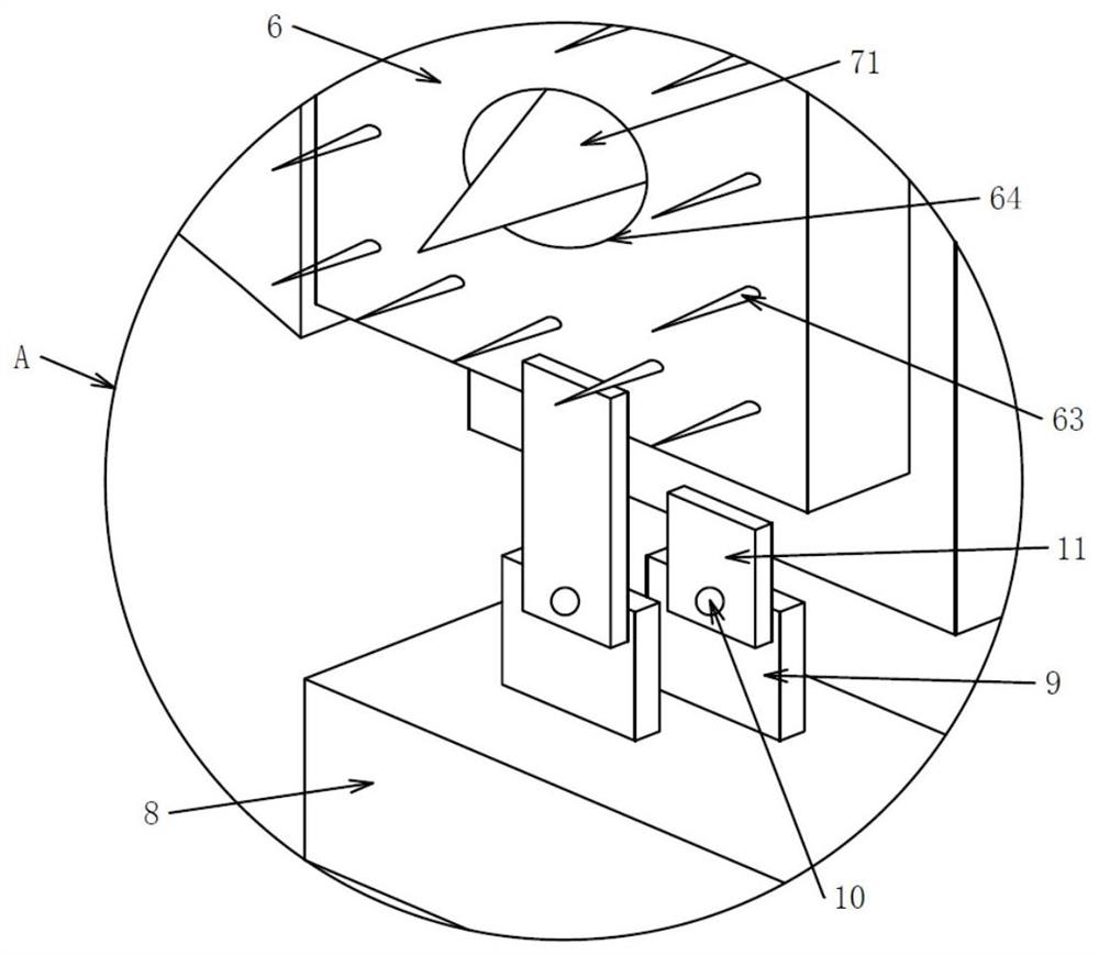
[0032] see Figure 1-10 , the present invention provides a technical solution:

[0033] A small outdoor power cabinet, including a power cabinet 1. In this embodiment, the power cabinet 1 with a total weight of 40 kg is taken as an example. The upper part of the power cabinet 1 is fixedly connected with the installation column 2, and the installation column 2 is provided with two, two The installation column 2 is installed on the top side of the power cabinet...


PUM


Abstract

The invention discloses a small outdoor power cabinet. The small outdoor power cabinet comprises a power cabinet. A mounting column is fixedly connected to the upper part of the power cabinet. The mounting column is sequentially sleeved with two rotating sleeves from top to bottom. The rotating sleeves are rotatably connected with the mounting columns through torsion springs, an extrusion plate isfixedly connected to the end, away from the corresponding rotating sleeve, of each rotating plate on the upper side, the tree attaching plates are movably connected with the extrusion plates and arranged on the front side in the rotating direction of the corresponding rotating sleeve, and projections of the tree attaching plates and projections of the extrusion plates in the horizontal directionhave overlapped parts. In conclusion, through an energy storage mode, the two hands for knocking screws into nails are liberated, the diameter of an installed trunk does not need to be considered anymore, a single person can install the electric power cabinet, the tree attaching plate and extrusion plate double-plate matched rotary nail entering mode is adopted, the electric power cabinet can bebetter inserted into the trunk, larger bearing force is provided, and the electric power cabinet is prevented from falling off after being installed.

Description

technical field [0001] The invention relates to the technical field of power cabinets, in particular to a small outdoor power cabinet. Background technique [0002] With the rapid development of power technology, the power cabinet is a commonly used power infrastructure, which is equipped with a large number of power components, and it is slowly put into use in cities and villages. However, most power cabinets use Installing directly on the ground takes up a lot of space and is not practical in some small areas. For example, the existing outdoor power cabinet with application number 201820045656.9 adopts a base and is directly installed on the ground. It is very complicated and inconvenient, and takes up a lot of space. [0003] In order to solve the problem of occupying space, there are also professional hoop equipment, which can directly install small electrical cabinets on the trunk. [0004] For example, the hoop device such as the application number 201821229119.6 is ...

Claims


Application Information

Patent Timeline
Patent Type & Authority Patents(China)
IPC IPC(8): H02B1/30
CPCH02B1/30
Inventor 沈梦然
Owner SUZHOU QIHUA MACHINERY & ELECTRICAL EQUIP
Why Eureka
Try Eureka