[0024] The following figures will further explain and illustrate the present invention:
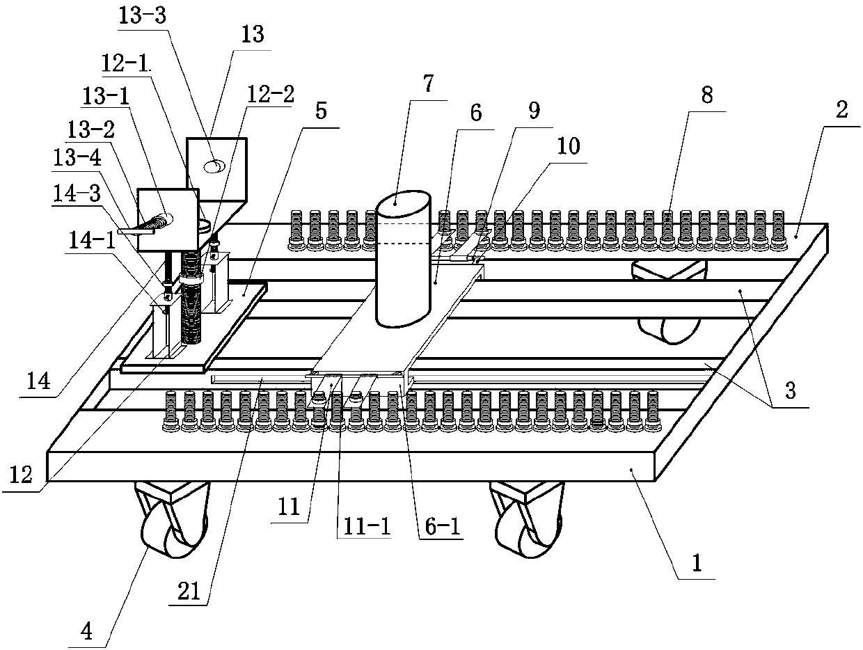
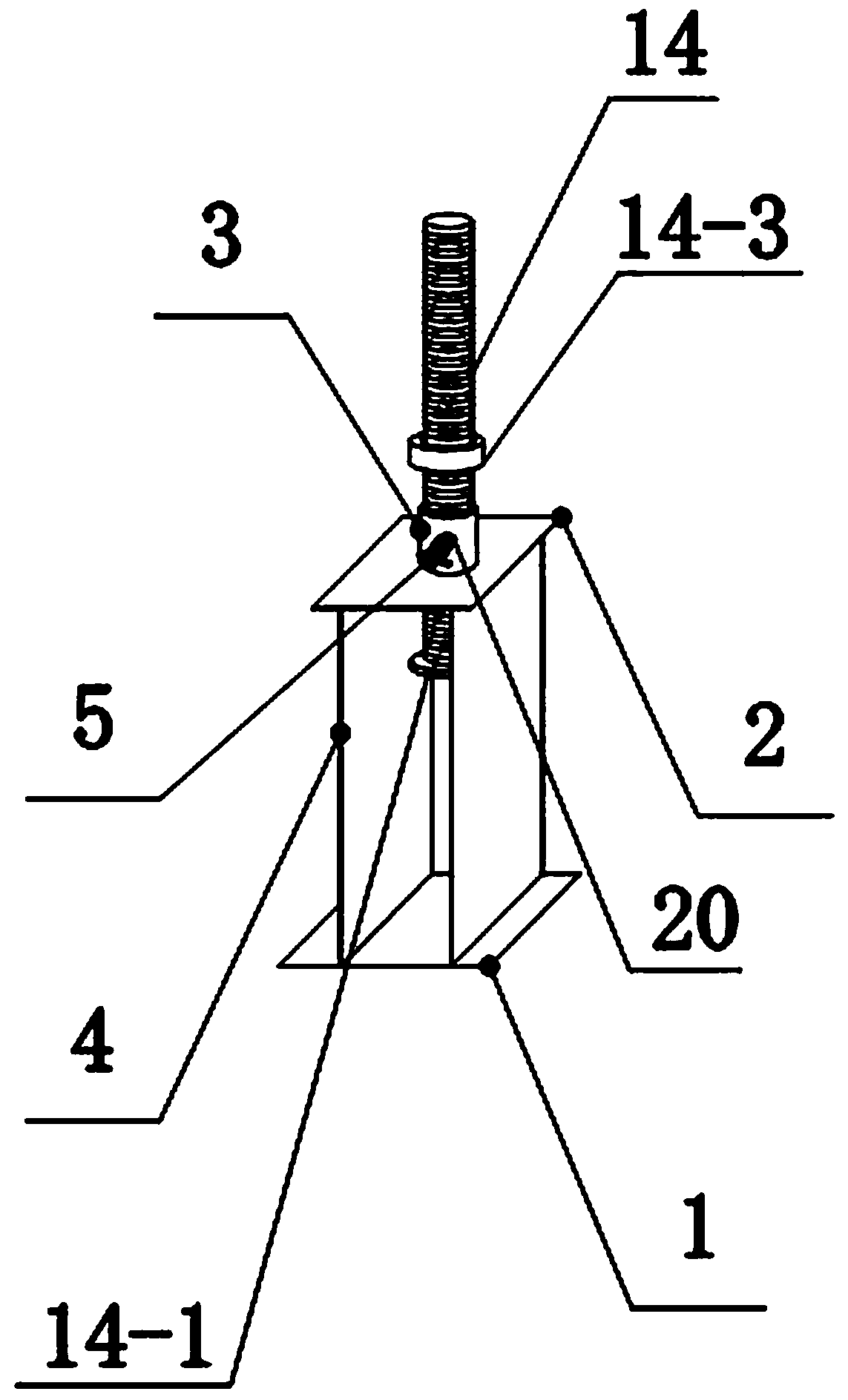
[0025] See Figure 1-Figure 3 , A wire crimping platform assembly, comprising a bottom frame 1, a fixed plate 2, a connecting rod 3, a moving plate 6 and a hydraulic wire crimping pliers 7. There are two fixed plates 2 which are respectively welded on the upper side of the bottom frame 1. And the inside of the lower side; there are two connecting rods 3, which are respectively welded to the inner side of the two bottom frames 1, and the two ends of the two connecting rods 3 are respectively fixedly connected to the inner wall of the bottom frame 1; two connections A bottom plate 5 is provided between the left side of the rod 3, and a wire adjustment mechanism is provided on the bottom plate 5; the two connecting rods 3 on the right side of the bottom plate 5 are slidably connected with a moving plate 6, and both ends of the moving plate 6 are fixed The “L”-shaped plates 6-1 are connected, and the ends of the bottom surfaces of the two “L”-shaped plates 6-1 are slidably connected to the corresponding moving grooves 21; the outer parts of the two “L”-shaped plates 6-1 are respectively A columnar support rod 9 is connected by a connecting block 10, and two sliding pipe sleeves 11-1 are sleeved on each columnar support rod 9, and a limit plate 11 is movably hinged outside each sliding pipe sleeve 11-1, A positioning hole is provided at the end of each limiting plate 11; a set of positioning bolts is provided on each fixing plate 2, and each set of positioning bolts is mainly composed of at least ten bolt rods 8, which are provided at the bottom of each bolt rod 8. There are bolt bases, each bolt base is fixedly connected with the fixed plate 2, and a matching nut is arranged on each bolt rod 8. The hydraulic wire crimping pliers 7 are fixedly arranged on the moving plate 6; each fixed plate 2 An adjustable roller mechanism is fixedly connected to the bottom of each limit plate 11; the position of the positioning hole at the end of each limit plate 11 corresponds to the position of the bolt rod 8 provided on the fixed plate 2, and the inner diameter of the positioning hole at the end of the limit plate 11 is larger than that of the bolt The diameter of the rod 8; the wire adjustment mechanism is mainly composed of a first positioning screw 12, a "U"-shaped wire slot 13, a wire positioning rod 13-2 and a positioning bracket. The bottom of the first positioning screw 12 is fixedly arranged in the center of the bottom plate 5. Position, a matching first nut 12-2 is provided on the first positioning screw 12, a stop block 12-1 with a circular cross-section is provided on the top of the first positioning screw 12, and the "U"-shaped cable groove 13 passes A hole arranged at the center of the bottom of the groove is sleeved on the first positioning screw 12; a guide tube 13-1 with internal threads is provided on the outside of the baffles on both sides of the "U"-shaped wire clamping groove 13, respectively. The guide tube 13-1 corresponds to the position on the baffle plate on both sides of the "U"-shaped cable groove 13 with through holes of the same diameter; a second threaded rod 13-2 is inserted into the guide tube 13-1, the second The threaded rod 13-2 and the guide tube 13-1 are connected by screw rotation; a second positioning block 13-2 is provided at the inner end of the second threaded rod 13-2, and the second threaded rod 13-2 A second handle 13-4 is provided at the end; a third threaded rod 14 is welded to both ends of the bottom of the "U"-shaped cable groove 13, and the bottom end of each third threaded rod 14 is fixedly connected with a circular section The third limiting block 14-1 is inserted into the positioning bracket at the lower end of each third threaded rod 14; a matching third nut 14-3 is provided on the third threaded rod 14 above the positioning bracket; Set up The inner diameter of the hole at the bottom center of the "U"-shaped cable groove 13 is greater than the diameter of the first positioning screw 12 and smaller than the diameter of the circular section of the stop block 12-1; the first nut 12-2 is located in the "U" ”Type cable groove 13 on the first positioning screw 12; the positioning bracket is mainly composed of a bottom positioning plate 15, a supporting vertical plate 18 and a top positioning plate 16. There are two supporting vertical plates 18, which are respectively set on the bottom positioning plate 15. The top positioning plate 16 is provided at the bottom of the two supporting vertical plates 18; a second guide tube 17 with internal threads is provided at the center of the top of the top positioning plate 16, and the second guide tube 17 corresponds to the top positioning The position of the plate 16 is dug with a through hole of the same diameter, the third threaded rod 14 is inserted in the second guide tube 17, and the circular cross section of the third limiting block 14-1 is larger than the inner diameter of the second guide tube 17; The three limiting blocks 14-1 are located between the two supporting vertical plates 18 below the second guide tube 17; a third guide tube 20 with internal threads is provided on the outside of the second guide tube 17, and the third guide tube 20 Corresponding to the position on the second guide tube 17 is provided with a through hole of the same diameter, and a fourth threaded rod 19 with a handle is provided in the through hole; there are four adjustable roller mechanisms, and the two ends of the bottom of each fixed plate 2 Two adjustable roller mechanisms are provided; each adjustable roller mechanism is mainly composed of a wheel 4, a roller bracket 4-7, a fifth screw 4-1 and a second "U"-shaped groove 4-2. The wheel 4 passes through the center. The shaft is arranged between the two roller brackets 4-7, the fifth screw 4-1 is arranged at the center of the top of the roller bracket 4-7, and a belt is provided on the inner side of the bottom groove surface of the second "U" groove 4-2. The fourth guide tube 4-4 with internal threads, the top of the fifth screw 4-1 is inserted into the fourth guide tube 4-4 through the thread rotation, and the bottom end of the fourth guide tube 4-4 is provided with a circle The fourth limit block 4-5 of circular cross section; the diameter of the fourth limit block 4-5 of circular cross section is larger than the outer diameter of the fourth guide tube 4-4; The inner diameter of the guide tube 4-4 is matched; the bottom of the second "U"-shaped groove 4-2 is provided with a top connecting plate 4-3, and the top connecting plate 4-3 is fixedly connected to the bottom of the fixing plate 2; A matching fifth nut 4-6 is provided on the fifth screw 4-1 below the two "U"-shaped grooves 4-2; the outer diameter of the third threaded rod 14 is smaller than the inner diameter of the second guide tube 17.
[0026] The hydraulic wire crimping tool 7 described above is an existing device.
[0027] When in use, the positioning hole at the end of the limit plate 11 is sleeved on the corresponding bolt rod 8, and the limit plate 11 is in a parallel state; by screwing the matching nut on the bolt rod 8 to the bottom of the limit plate 1, In addition, a matching nut is screwed on the bolt rod 8 above the limiting plate 11 to complete the positioning of the moving plate 6.
[0028] working principle:
[0029] 1. The use of adjustable rollers:
[0030] According to the ground conditions, screw the fifth nut 4-6 to the bottom end of the fifth screw 4-1, and move up and down on the fifth screw 4-1 through the second "U"-shaped groove 4-2 to complete the fixing plate 2. The distance from the bottom to the ground; after adjustment, screw the fifth nut 4 to the bottom of the second "U"-shaped groove 4-2.
[0031] 2. Use of wire adjusting mechanism:
[0032] Place the wire in the "U"-shaped wire-clamping groove, and set a second threaded rod and guide tube on both sides of the "U"-shaped wire-clamping groove. The second threaded rod is rotated in the guide tube to the "U"-shaped wire-clamping groove. The inner wire is clamped to complete the positioning of the wire; the "U"-shaped wire clamping groove can move up and down on the first positioning screw freely, and the third threaded rod will also be at the second position of the center position of the positioning plate on the top of the positioning bracket. Move up and down inside the guide tube, by screwing the first nut to the bottom of the "U"-shaped wire slot to complete the fixing of the "U"-shaped wire slot; by screwing the third nut to the top of the second guide tube , To avoid the sliding of the third threaded rod, and complete the positioning of the third threaded rod by arranging a fourth threaded rod with a handle and a third guide tube on the outer wall of the second guide tube.
[0033] 3. Moving and fixing of the mobile board:
[0034] The moving plate can be moved left and right through the moving groove 21. When the moving plate is moved to a desired position, the positioning hole at the end of the limit plate 11 is sleeved on the corresponding bolt rod 8, and the limit plate 11 is in a parallel state; By screwing a matching nut on the bolt rod 8 to the bottom of the limiting plate 1, and screwing a matching nut on the bolt rod 8 above the limiting plate 11, the fixing of the moving plate 6 is completed.
[0035] The invention is reasonable in design, simple in structure, and convenient to use. It is proved by on-site actual operation that the original work of 6-8 people can now be completed by 2 people, which can save a lot of manpower and material resources and significantly improve work efficiency. The flexible wire crimping platform trolley also avoids the time-consuming and laborious phenomenon of manual handling of wires due to objective factors such as large cross-sectional area, long length and heavier weight of the wires during the construction process; It is not strong, causing the wire to rub against the ground when handling the wire, causing the wire to be scratched, resulting in common quality problems such as burrs. After the soft wire is installed, the device will produce sharp discharge when the device is powered on, and cause damage to the equipment clip and hardware. Avoid secondary Rework greatly improves the quality of construction and beautiful craftsmanship.