Electric brush for traction motor

A technology for traction motors and brushes, applied in electromechanical devices, electrical components, etc., can solve problems such as high wear of commutators or slip rings, lack of brush positioning devices, and large loss of carbon brushes, so as to reduce losses and save purchases Cost, the effect of saving the cost of use

Active Publication Date: 2021-11-09
辽宁红德电碳制品有限公司
View PDF5 Cites 0 Cited by
  • Summary
  • Abstract
  • Description
  • Claims
  • Application Information

AI Technical Summary

Problems solved by technology

[0002] Brushes are widely used in many electrical equipment. It is a device that transmits energy and signals between the fixed part and the rotating part of a motor, engine or other rotating machinery. Its components are mainly composed of graphite, resin adhesive and other auxiliary materials. agent, and then made by sintering, conventional carbon brushes generally have problems such as large loss and short service life during use;
[0003] The brushes are mostly assembled on the commutator or slip ring, which is a sliding contact body, which needs to have characteristics such as smoothness, wear resistance, and good conductivity. According to different applications, they are either partial metal parts (copper, silver, molybdenum, etc.) ), rich or entirely made of metal, in actual use, a slip ring is usually equipped with at least two brushes, to avoid an open circuit due to poor contact of a single brush, in the prior art, between the traction motor and the commutator The intermediate frame is often used for connection, and the intermediate frame lacks a positioning device for the brush, which often makes the brush in a suspended state, and is only connected to the commutator or slip ring through the connecting end at the top of the brush. The wear of the commutator or slip ring is relatively high. In view of these situations, in order to avoid the above-mentioned technical problems, it is necessary to provide a brush for traction motors to overcome the defects in the prior art

Method used


Image

  • Electric brush for traction motor
  • Electric brush for traction motor
  • Electric brush for traction motor

Examples


Embodiment Construction

[0016] The following will clearly and completely describe the technical solutions in the embodiments of the present invention with reference to the accompanying drawings in the embodiments of the present invention. Obviously, the described embodiments are only some, not all, embodiments of the present invention. Based on the embodiments of the present invention, all other embodiments obtained by persons of ordinary skill in the art without making creative efforts belong to the protection scope of the present invention.

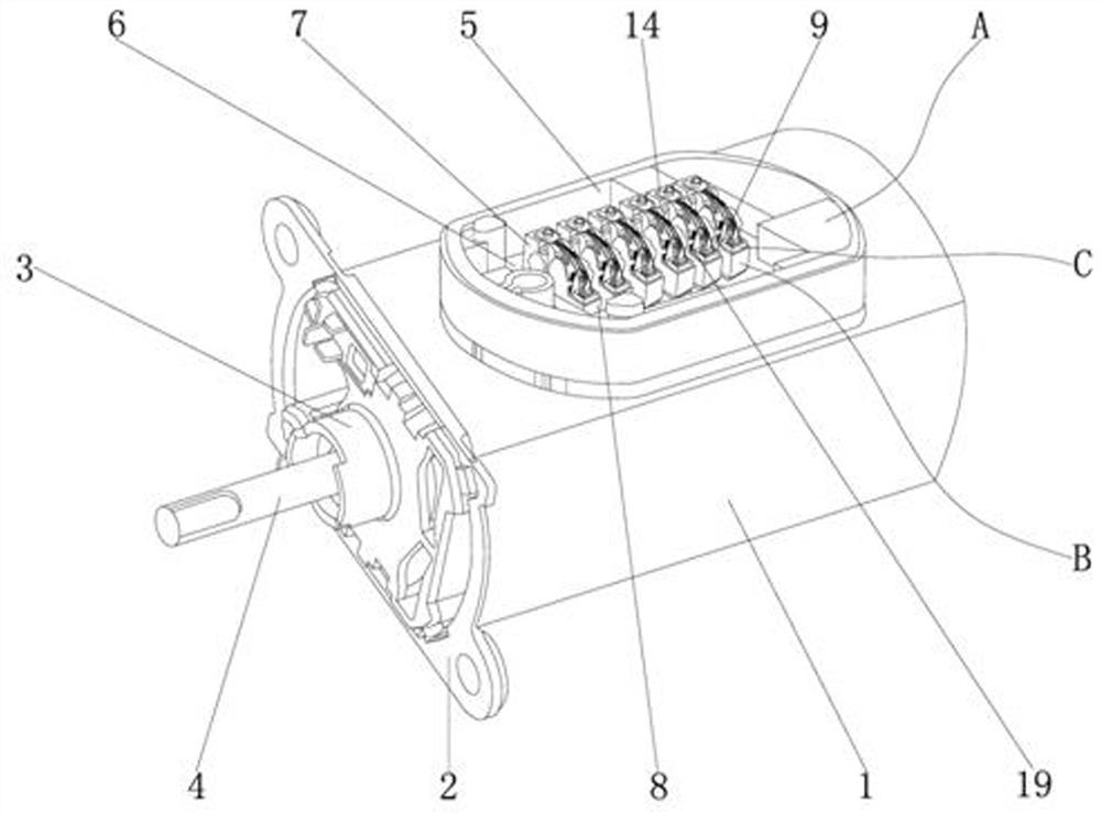
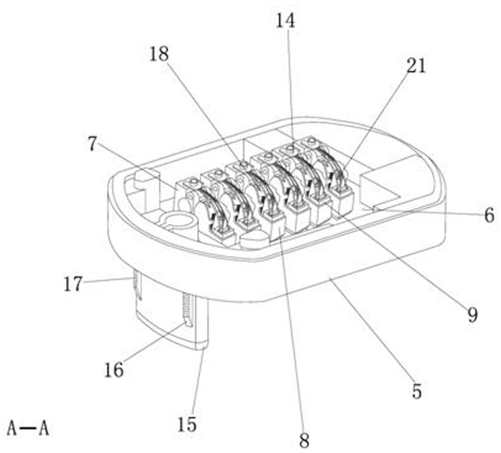
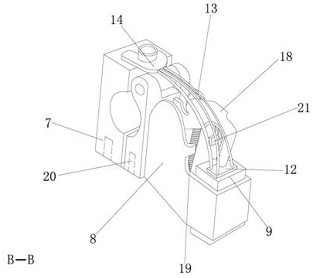
[0017] see Figure 1-4 , the present invention provides a technical solution: a traction motor brush, including a traction motor 1, the model of the traction motor 1 is DCZ01QY, used for traction locomotives, the left side of the traction motor 1 is provided with a fixed plate 2, the fixed plate 2 It is used to fix the traction motor 1 on the locomotive, and the fixed plate 2 is bolted to the traction motor 1, and the interior of the traction motor 1 is provid...


PUM


Abstract

The invention discloses a brush for a traction motor, which comprises a traction motor, a fixed plate is arranged on the left side of the traction motor, and the fixed plate is connected with bolts of the traction motor, and a rotor is arranged inside the traction motor, and A slip ring is set in the sleeve, and the slip ring is connected with the rotor bolts, and the rotor is connected with the traction motor key, and the top of the traction motor is provided with a brush fixing frame, and the left bottom of the brush fixing frame is provided with a plug-in plate, and the plug-in The board and the brush fixing frame are integrated, and the left side of the plug-in board is provided with a top block. The brush used for the traction motor, through the cooperation between the brush fixing frame and the brush holder, under the action of the fixing plate, the brush cover and the pressure spring, the connection between the brush and the slip ring of the traction motor is more firm, And it is convenient to disassemble and replace, improves the product quality of the electric brush for the traction motor, saves the purchase cost of the user, avoids the resource waste of the electric brush, and is suitable for popularization and use.

Description

technical field [0001] The invention relates to the technical field of traction motors, in particular to a brush for traction motors. Background technique [0002] Brushes are widely used in many electrical equipment. It is a device that transmits energy and signals between the fixed part and the rotating part of a motor, engine or other rotating machinery. Its components are mainly composed of graphite, resin adhesive and other auxiliary materials. agent, and then made by sintering, conventional carbon brushes generally have problems such as large loss and short service life during use; [0003] The brushes are mostly assembled on the commutator or slip ring, which is a sliding contact body, which needs to have characteristics such as smoothness, wear resistance, and good conductivity. According to different applications, they are either partial metal parts (copper, silver, molybdenum, etc.) ), rich or entirely made of metal, in actual use, a slip ring is usually equipped ...

Claims


Application Information

Patent Timeline
Patent Type & Authority Patents(China)
IPC IPC(8): H02K13/00
CPCH02K13/003
Inventor 柳国庆王宪萍张旭
Owner 辽宁红德电碳制品有限公司
Why Eureka
Try Eureka