
Liver scrabbling device for laparoscopic surgery

A laparoscopic and surgical technology, applied in the field of medical devices, can solve the problems of inconvenient precise control of the range of movement of the fan, easy to bump into other organs, and insufficient width of the force-bearing surface, so as to avoid inaccurate movement control and the force-bearing surface of the liver. wide, to avoid damage to the effect

Active Publication Date: 2020-03-27
THE FIRST AFFILIATED HOSPITAL HENGYANG MEDICAL SCHOOL UNIV OF SOUTH CHINA
View PDF19 Cites 0 Cited by
  • Summary
  • Abstract
  • Description
  • Claims
  • Application Information

AI Technical Summary

Problems solved by technology

The device has a complicated structure and is not suitable for use as a disposable surgical instrument
Moreover, the so-called "fans" in the above-mentioned documents are actually strip-shaped long rods one by one. The rear ends of these long strip-shaped rods are hinged together. This leads to a large opening of the front end (sometimes, the front end of the fan blade is opened too wide at once, and it is easy to bump into other organs or scratch the liver lobe), which is not convenient for precise control of the movement range of the front end of the fan blade
In addition, because it only relies on a few long "fans" to contact the liver, the force-bearing surface is still not wide enough, and the reliability needs to be further improved

Method used


Image

  • Liver scrabbling device for laparoscopic surgery
  • Liver scrabbling device for laparoscopic surgery
  • Liver scrabbling device for laparoscopic surgery

Examples


Embodiment Construction

[0036] In describing the present invention, it is to be understood that the terms "middle", "upper", "lower", "front", "rear", "left", "right", "top", "bottom", " The orientation or positional relationship indicated by "inner", "outer", etc. is based on the orientation or positional relationship shown in the drawings, which is only for the convenience of describing the present invention and simplifying the description, rather than indicating or implying that the referred device or element must have a specific orientation, are constructed and operate in a particular orientation and therefore are not to be construed as limiting the invention.

[0037] In order to make it easier for those skilled in the art to understand the concept of the present invention more clearly, it will be further described below in conjunction with the embodiments and the accompanying drawings.

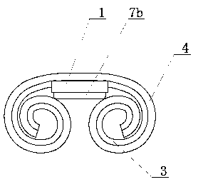
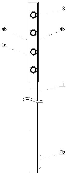
[0038] Figure 1-5 It shows the specific structure of the laparoscopic liver chopping device involved in th...


PUM

PropertyMeasurementUnit
Heightaaaaaaaaaa
Diameteraaaaaaaaaa

Abstract

The invention discloses a liver scrabbling device for a laparoscopic surgery, and relates to the technical field of medical instruments. The liver scrabbling device comprises a support, telescopic rods, hoses, a liver scrabbling sheet, springs, pull wires and a take-up unit, wherein the rear ends of the telescopic rods are connected with the support; the front ends of the hoses are closed; the rear ends of the hoses are fixedly connected with the side wall of the support; the rear-end openings of the hoses face the telescopic rods; the telescopic rods can be inserted from the rear-end openingsof the hoses when extending; the liver scrabbling sheet comprises a bottom sheet which is fixedly connected with the support; the hoses are fixedly connected with the bottom sheet; the left half partof the bottom sheet is wound from left to right; the right half part of the bottom sheet is wound into a scroll shape from right to left; each spring is arranged in a telescopic rod; each pull wire is arranged in a telescopic rod in a penetrating manner; when the pull wires are pulled backwards, the telescopic rods can be retracted and shortened, and the springs can be compressed; the take-up unit comprises a take-up wheel; the rear ends of all the pull wires are wound on the take-up wheel; the pull wires can be wound and unwound by rotation of the take-up wheel; the liver scrabbling sheet can be wound and folded through the resilience force of the bottom sheet; and when the springs push the telescopic rods to extend and be inserted into the hoses, the bottom sheet is stretched to be straight, and the liver scrabbling sheet is unfolded.

Description

technical field [0001] The invention relates to the technical field of medical devices, in particular to a laparoscopic surgery liver-stealing device. Background technique [0002] During laparoscopic surgery, the resection of the posterior lobe of the right liver, the eighth segment of the liver, and the right hemihepatectomy is difficult due to the difficulty in exposing the operative field and handling the second hepatic hilum. It requires doctors with rich experience and skills in laparoscopic liver resection to successfully complete it. During the operation, whether the operative field can be fully exposed is a very critical part. In the past, two clamps were usually used to clamp the gauze against the liver lobe to crawl the liver, so that the operative field was exposed. Due to the force Due to the limited area, this method of grilling the liver is inconvenient to operate, and if you do not pay attention during the operation, it is easy to damage the liver lobe by cla...

Claims


Application Information

Patent Timeline
IPC IPC(8): A61B17/02
CPCA61B17/0218
Inventor 陈国栋
Owner THE FIRST AFFILIATED HOSPITAL HENGYANG MEDICAL SCHOOL UNIV OF SOUTH CHINA
Learn More