Extraction device for pharmacy

The technology of an extraction device and an extraction tank is applied in the field of pharmaceutical extraction devices, which can solve the problems of the influence of drug extraction and uncontrollable temperature, and achieve the effects of preventing drug spillage, preventing the reduction of heating efficiency and improving extraction efficiency.

Inactive Publication Date: 2020-03-27
湖北正通药业有限公司
View PDF1 Cites 2 Cited by
  • Summary
  • Abstract
  • Description
  • Claims
  • Application Information

AI Technical Summary

Problems solved by technology

A pharmaceutical extraction device in the above-mentioned patent has the following disadvantages: when the existing device extracts the medicament, it usually directly heats the medicament, but the temperature is uncontrollable due to direct heating, so the extraction of the medicament make an impact

Method used


Image

  • Extraction device for pharmacy
  • Extraction device for pharmacy
  • Extraction device for pharmacy

Examples


Embodiment 1

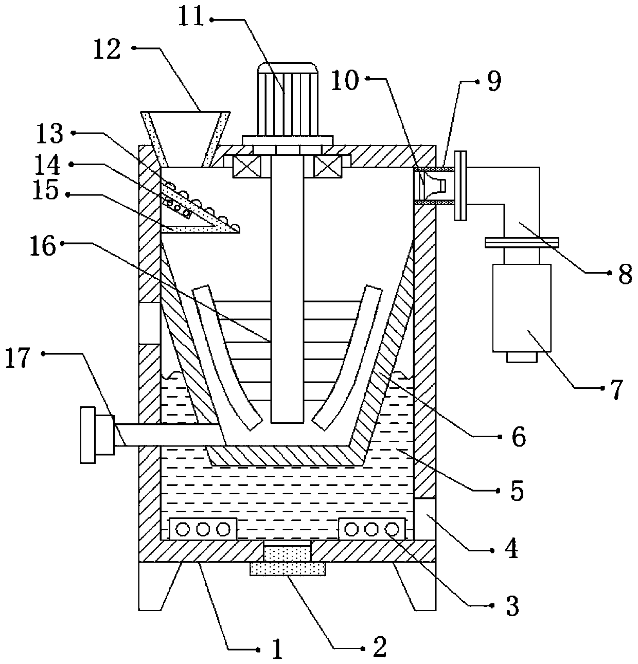
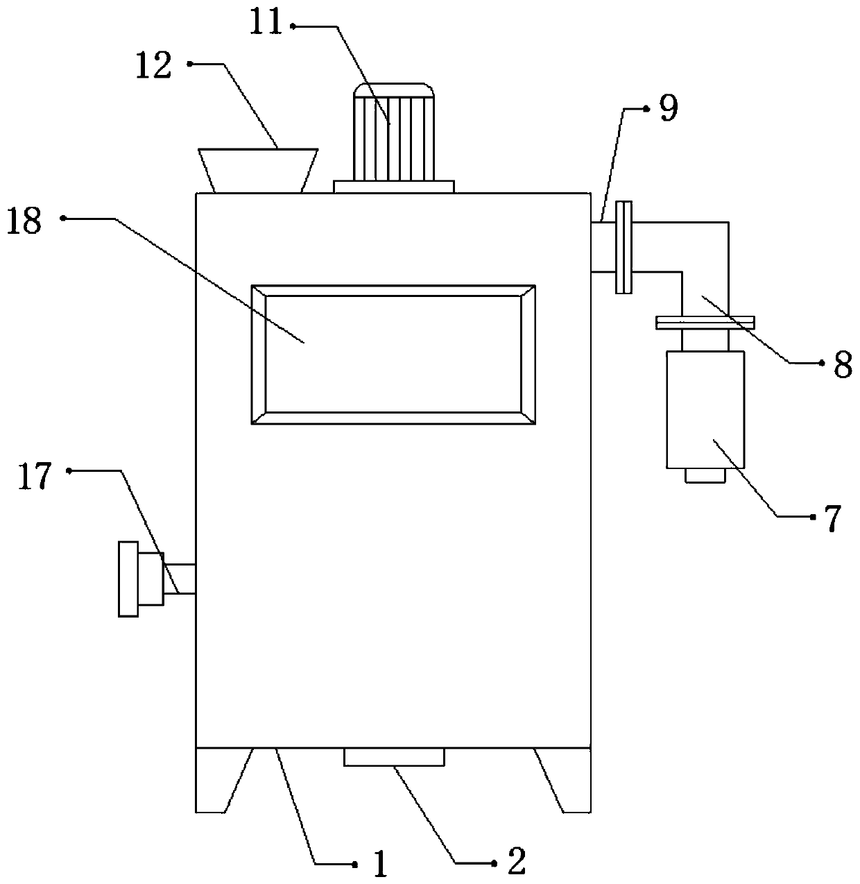
[0027] refer to Figure 1-2 , an extraction device for pharmaceuticals, comprising an extraction tank 1, the inner wall of the extraction tank 1 is connected with an inner tank 6 by bolts, and the inner tank 6 is made of a heat-conducting material, and a heating chamber 5 is left between the inner tank 6 and the extraction tank 1, and One side inner wall of the heating chamber 5 has a water inlet, and the side inner wall and the bottom inner wall of the heating chamber 5 are all provided with a water outlet 4, and the inner wall of the water outlet 4 and the inner wall of the water inlet are all provided with a sealing plug 2, and the heating chamber 5 Both sides of the inner wall of the bottom are connected with a heater 3 by bolts, one side of the outer wall of the top of the extraction tank 1 is provided with a feed port, and the inner wall of the feed port is connected with a feed hopper 12 by bolts, and the outer wall of one side of the extraction tank 1 is An exhaust pip...

Embodiment 2

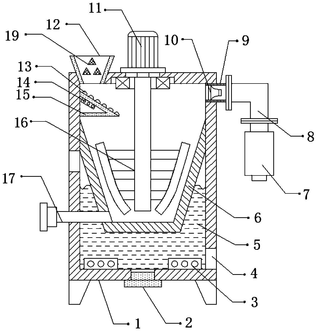
[0031] refer to image 3 , an extracting device for pharmaceutical use. Compared with Embodiment 1, the inner wall of the feed hopper 12 is connected with a stop bar 19 by bolts, and the stop bar 19 is distributed randomly.

[0032] Working principle: when in use, the medicament is filled into the extraction tank 1 through the feed hopper 12, the flow speed of the medicament can be slowed down by the bump 13 and the blocking rod 19, so as to improve the extraction efficiency of the medicament, and the heating block 14 can Carry out pre-heating treatment on the medicament to prevent the heating efficiency of the device from being reduced due to too much medicament, inject an appropriate amount of water into the heating chamber 5 through the water inlet, and heat the water through the heater 3, thereby heating and extracting the medicament, During this period, the deceleration motor 11 will drive the stirring frame 16 to rotate, so as to stir the medicament, so that the medicame...


PUM


Abstract

The invention discloses an extraction device for pharmacy. The extraction device comprises an extraction tank. An inner tank is fixed on the inner wall of the extraction tank. The inner tank is made of a thermo-conductive material. A heating cavity is formed between the inner tank and the extraction tank. The inner wall of one side of the heating cavity is provided with a water inlet. The inner wall of one side of the heating cavity and the inner wall of the bottom of the heating cavity are both provided with a water outlet. The inner walls of the water outlets and the inner wall of the waterinlet are all provided with a sealing plug. Two sides of the inner wall of the bottom of the heating cavity are both fixedly provided with a heater. One side of the outer wall of the top of the extraction tank is provided with a feed inlet. A feed hopper is fixed on the inner wall of the feed inlet. The outer wall of one side of the extraction tank is provided with an exhaust pipe. The provided extraction device can avoid the situation that the temperature in direction heating is uncontrollable and the extraction is influenced; and moreover, the extraction device can inhibit the degradation ofheating efficiency. The phenomenon that the medicaments are spilled out due to the quick stirring speed of a stirring rack, or the work efficiency is low due to the low stirring speed of the stirringrack can be avoided.

Description

technical field [0001] The invention relates to the technical field of pharmaceutical engineering, in particular to a pharmaceutical extraction device. Background technique [0002] Simply speaking, pharmaceutical extraction equipment uses extraction equipment to extract the essence of traditional Chinese medicine. The components of pharmaceutical extraction equipment can be divided into extraction tanks, condensers, coolers, separators, filters, and slag door pneumatic control systems. [0003] After retrieval, the Chinese patent authorization number is CN208660416U, which discloses a pharmaceutical extraction device, including a heating box, a heat conduction plate is fixedly installed at the lower end of the heat conduction plate, and a flame nozzle is arranged below the heat conduction plate. The flame sprayer is fixedly installed on the right side of the support block, the fuel tank is fixedly installed on the right side of the support block, the lower end of the suppor...

Claims


Application Information

Patent Timeline
Patent Type & Authority Applications(China)
IPC IPC(8): B01D11/02
CPCB01D11/0207B01D11/0257
Inventor 姜正清
Owner 湖北正通药业有限公司
Why Eureka
Try Eureka