Hotel kitchen lampblack collecting and purifying device

A technology for purification devices and kitchens, which is applied to combined devices, grease/oily substance/float removal devices, chemical instruments and methods, etc., can solve the problems of high maintenance cost, difficult maintenance, short purification effect, etc., and achieve low maintenance cost. , good effect, long-lasting effect of treatment

Inactive Publication Date: 2020-03-27
JIANGSU ZHONGXING HOTEL FACILITIES
6 Cites 0 Cited by

AI-Extracted Technical Summary

Problems solved by technology

[0004] The purpose of the present invention is to provide a hotel kitchen oil fume collection and purification device to ...

Abstract

The invention discloses a hotel kitchen lampblack collecting and purifying device, which comprises an exhaust fume collecting hood, an air inlet duct, a case, a motor, an exhaust duct, an exhaust hoodand fans. The fans are mounted on the left side and the right side of the top end of an inner cavity of the exhaust fume collecting hood. The air inlet duct is welded at the top end of the exhaust fume collecting hood, and the air inlet channel is connected with the fans. The bottom end of the air inlet duct is connected with the case in an inserted mode. The motor is welded to the center of therear side of the upper surface of the case in the left-right direction through screws. The right end of the exhaust duct is connected with the exhaust hood through screws. Clamping grooves are weldedto the bottom ends of the left side and the right side of the inner cavity of the exhaust fume collecting hood in the front-back direction. Outer frames are inserted into inner cavities of the two clamping grooves. Dust collecting nets are connected to the rear sides of the bottom ends of the outer frames in the front-back direction through hinges. A water inlet pipe is in threaded connection withthe left side of the bottom end of the front side of the case in the front-back direction. The hotel kitchen lampblack collecting and purifying device is better in lampblack filtering effect, more durable in treatment effect, convenient to maintain, low in maintenance cost and beneficial to popularization.

Application Domain

Combination devicesGas treatment +2

Technology Topic

Exhaust fumesStructural engineering +2

Image

  • Hotel kitchen lampblack collecting and purifying device
  • Hotel kitchen lampblack collecting and purifying device
  • Hotel kitchen lampblack collecting and purifying device

Examples

  • Experimental program(1)

Example Embodiment

[0018] The following will clearly and completely describe the technical solutions in the embodiments of the present invention with reference to the accompanying drawings in the embodiments of the present invention. Obviously, the described embodiments are only some, not all, embodiments of the present invention. Based on the embodiments of the present invention, all other embodiments obtained by persons of ordinary skill in the art without making creative efforts belong to the protection scope of the present invention.
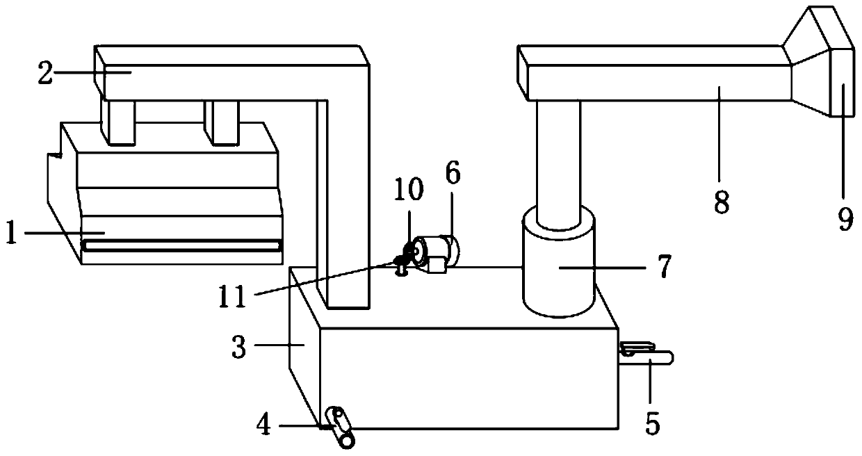
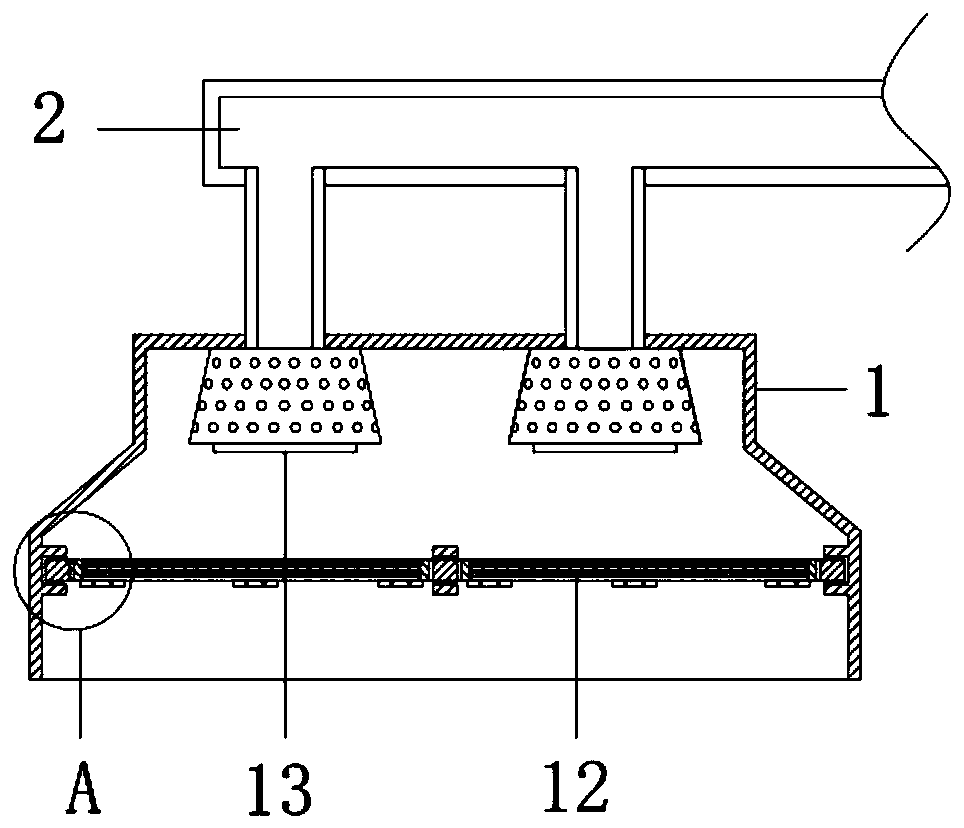
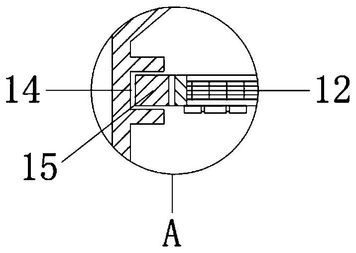
[0019] see Figure 1-5 , the present invention provides a technical solution: a hotel kitchen oil fume collection and purification device, including a smoke collection hood 1, an air inlet duct 2, a casing 3, a motor 6, an exhaust duct 8, an exhaust hood 9 and a fan 13, the collection Fans 13 are installed on the left and right sides of the top of the inner cavity of the fume hood 1, and the fans 13 generate a conveying force sufficient to transport the smoke into the casing 3 and out of the exhaust hood 18, and the top of the fume collection hood 1 is welded with an air inlet duct 2, and the air inlet duct 2 is connected with the fan 13, the section of the air inlet duct 2 is L-shaped, the bottom end of the air inlet duct 2 is plugged into the casing 3, and the center position of the rear side of the upper surface of the casing 3 is welded along the left and right direction The screw is connected with a motor 6, and the motor 6 is a stepping motor, which can precisely control the rotating speed to adapt to the work requirements. The ends are welded with draw-in slots 14 along the front and back directions, and the outer frame 15 is supported by the draw-in slots 14. The inner cavity of the two draw-in slots 14 is inserted with an outer frame 15, and the dust collection net 12 is assembled through the outer frame 15, and the outer frame 15 The rear side of the bottom end is connected with a dust collection net 12 through a hinge along the front and back direction, and the dust collection net 12 can be pulled out of the smoke collection cover 1 through the outer frame 15, so that the dust collection net 12 can move around the outer frame 15, thereby facilitating The dust collecting net 12 is cleaned, thereby facilitating the regular maintenance of the device and reducing the workload. The left side of the bottom end of the front side of the casing 3 is screwed with the water inlet pipe 4 along the front and rear direction, and the center position of the bottom end of the right side of the casing 3 is along the Drainage pipe 5 is screwed in left and right directions, water inlet pipe 4 and drainage pipe 5 are connected with the inner cavity of casing 3, the bottom end of the outer wall of air inlet channel 2 extends into the inner cavity of casing 3 and is screwed with exhaust cover 18 , through the exhaust hood 18, the flue gas is discharged into the water in the form of bubbles, so that the flue gas and the water can be more fully contacted. The right side of the exhaust hood 18 is located at the top of the inner cavity of the casing 1 and is provided with a first baffle along the front and rear directions. 19. Through the first baffle 19, the contact time between the flue gas and the water is prolonged, and the flue gas and the water are further fully contacted. The second baffle 20 blocks the bubbles generated by the exhaust hood 18 through the second baffle 20 to prevent the bubbles from floating too slowly. The right side of the second baffle 20 is located between the center positions of the front and rear sides of the inner cavity of the casing 1 Two third baffles 22 are arranged successively along the left and right directions, and the oil on the water surface is blocked by the third baffles 22. The first rotating rod 23 is connected through the bearing, and the left and right ends of the outer wall of the first rotating rod 23 and the center position of the outer wall are all interference-fitted with the inner ring of the bearing. The outer rings of bearings are fixedly connected to the top ends of the sides, and the bottom ends of the left front side of the two third baffle plates 22 and the second baffle plate 20 are connected with the second rotating rod 24 through bearings along the left and right directions, and the second rotating rod 24 The left and right ends of the outer wall and the center of the outer wall are all interference-fitted with the inner ring of the bearing. The two third baffles 22 and the bottom of the left front side of the second baffle 20 are fixedly connected with the outer ring of the bearing. Between the baffle plates 22 and between the second baffle plate 20 and the third baffle plate 22, on the outer walls of the first rotating rod 23 and the second rotating rod 24 Conveyor belts 21 are installed, between the two third baffles 22 and between the second baffle 20 and the third baffle 22 are located on the rear side of the casing 1 along the left and right directions are provided with an oil discharge bucket 25, and the discharge The oil bucket 25 is located at the bottom of the first rotating rod 23 and extends out of the rear side of the outer wall of the casing 1. The oil is scraped off the conveyor belt 21 through the top of the oil discharge bucket 25, and the oil is discharged through the inner cavity of the oil discharge bucket 25. Exhaust, the left side of the outer wall of the first rotating rod 23 extends out of the left side of the second baffle plate 20 and is keyed to the first bevel gear 16, the left side of the first bevel gear 16 is located at the top of the inner cavity of the casing 1 and passes through The pin shaft is connected with a second bevel gear 26, and the first bevel gear 16 is engaged with the second bevel gear 26. The top end of the outer wall of the second bevel gear 26 extends out of the upper surface of the casing 1 and is keyed to the second Three bevel gears 11, the left output end of the motor 6 is keyed to the fourth bevel gear 10, and the third bevel gear 11 is meshed with the fourth bevel gear 10, and the center position on the right side of the upper surface of the casing 1 A filter housing 7 is welded along the up and down direction, and the filter housing 7 communicates with the inner chamber of the casing 1. A filter element 17 is installed in the inner cavity of the filter housing 7. The main component of the filter element 17 is activated carbon. Through the adsorption of the activated carbon 17, the Harmful substances in the flue gas are adsorbed, and the top of the filter housing 7 is welded with the exhaust duct 8 .
[0020] As a preferred solution, further, the outer rings of the two fans 13 are provided with anti-fouling covers, and the anti-pollution covers prevent oil pollution from invading the inside of the fans and causing damage.
[0021] As a preferred solution, further, the height of the oil discharge hopper 25 is higher than the top front side of the second baffle 20 to prevent water from entering the oil discharge hopper 25 .
[0022] As a preferred solution, further, the height of the second baffle plate 20 is the same as that of the drain pipe 5 , so as to prevent the water level from being too high and causing water to flow into the oil drain hopper 25 .
[0023] As a preferred solution, further, the heights of the two third baffles 22 are both higher than the second baffle 20, so that the third baffles 22 can block the oil on the water surface.
[0024] Its detailed connection means is a well-known technology in the art. The following mainly introduces the working principle and process, and the specific work is as follows.
[0025]During use, connect the external power supply of motor 6 and blower fan 13, connect the external water pipe of water inlet pipe 4 and drain pipe 5, pour water in the casing 3 by water inlet pipe 4, when the water level in the casing 3 is the same as that of the drain pipe 5 After the position is level, the drain pipe 5 discharges the water to keep the water level unchanged. The fan 13 sucks the oily fume into the fume collecting hood 1. The oily fume first passes through the dust collection net 12, and the dust collection net 12 filters the large particles of oil fume, and the oil fume passes through the fan. It is sent into the air inlet duct 2, and then enters the casing 3 through the air inlet duct 2, and the flue gas is evenly discharged in the form of small bubbles through the exhaust hood 18, so that it contacts with water evenly, and the oil in the flue gas is filtered out. The density of oil is lower than that of water, and the oil will float on the surface of the water, and the oil will be blocked on the left side of the third baffle 22 through the third baffle 22, and the water will pass through the bottom of the third baffle 22, and the filtered flue gas Pass above the third baffle plate 22, enter the filter housing 7, filter through the filter element 17, enter the exhaust duct 8, and finally discharge through the exhaust hood 9, and at the same time, the motor 6 drives the fourth bevel gear 10 to drive the third cone. The bevel gear 11 rotates, the third bevel gear 11 drives the second bevel gear 26 to drive the first bevel gear 16 to rotate, the first bevel gear 16 drives the first rotating rod 23 to drive the conveyor belt 21 to rotate, and the conveyor belt 21 drives The second rotary rod 24 rotates, and the conveyor belt 21 drives the oil blocked by the second baffle plate 22 on the water surface backwards, and the oil is scraped off through the contact surface between the top of the oil discharge bucket 25 and the bottom end of the conveyor belt 21, so as to continuously flow into the oil discharge In the bucket 25, the oil is discharged from the casing 1 through the oil discharge bucket 25, so that the oil and water are separated, and other harmful substances in the flue gas are adsorbed by the filter element 17 composed of activated carbon. This device is easy to maintain, simple in structure, easy to operate, and the treatment effect Durable, practical, and conducive to promotion.

PUM

no PUM

Description & Claims & Application Information

We can also present the details of the Description, Claims and Application information to help users get a comprehensive understanding of the technical details of the patent, such as background art, summary of invention, brief description of drawings, description of embodiments, and other original content. On the other hand, users can also determine the specific scope of protection of the technology through the list of claims; as well as understand the changes in the life cycle of the technology with the presentation of the patent timeline. Login to view more.

Similar technology patents

Defrosting method of air source heat pump water heater

ActiveCN106152643AProtect device securitygood effect
Owner:江苏鑫昊空调设备有限公司

Novel spraying agent for reducing indoor haze, and application thereof

InactiveCN104910866AExtensive sources of materialsgood effect
Owner:GUANGDONG UNIV OF TECH

Classification and recommendation of technical efficacy words

  • good effect
  • long-lasting treatment

Sterilizing effective antipruritic application agent

InactiveCN1989950Aavoid infectionlong-lasting treatment
Owner:TIANJIN WEALTH BIOENGINEERING SCI & TECH CO LTD
Why Eureka
Try Eureka