Stamping device for processing new energy automobile parts

A new energy vehicle and stamping device technology, applied in the direction of feeding device, positioning device, storage device, etc., can solve the problems of increasing the processing time of a single part, failing to meet safety production, safety hazards, etc., to improve processing efficiency, Ease of retrieving materials and improving safety

Inactive Publication Date: 2020-03-27
东营瑞尔泰机电科技有限公司
View PDF6 Cites 4 Cited by
  • Summary
  • Abstract
  • Description
  • Claims
  • Application Information

AI Technical Summary

Problems solved by technology

[0003] Stamping devices are often used in the processing of new energy auto parts, but most of the traditional stamping devices have a relatively simple structure. Generally, the stamping operation is mainly performed by a fixed lower die and an upper die that moves up and down. However, during the loading and unloading process, On the one hand, it increases the processing time of a single component. On the other hand, the operator needs to carry out loading and unloading operations under the upper mold, which has certain safety hazards, so it can no longer meet the needs of modern safe production.

Method used


Image

  • Stamping device for processing new energy automobile parts
  • Stamping device for processing new energy automobile parts
  • Stamping device for processing new energy automobile parts

Examples


Embodiment Construction

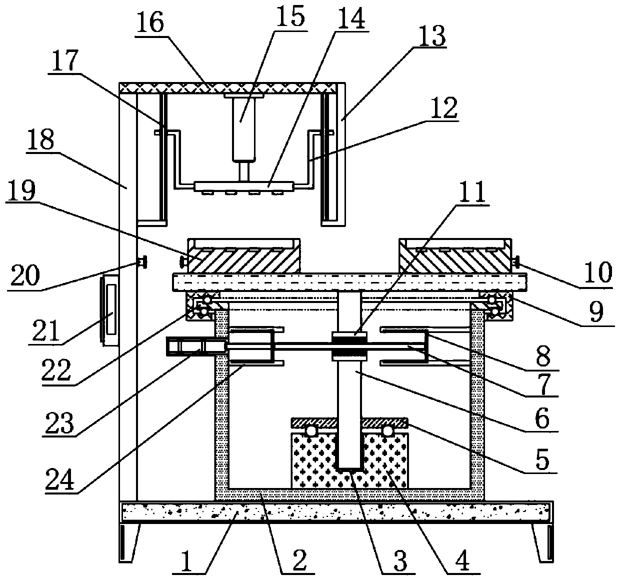
[0026] The following will clearly and completely describe the technical solutions in the embodiments of the present invention with reference to the accompanying drawings in the embodiments of the present invention. Obviously, the described embodiments are only some, not all, embodiments of the present invention.

[0027] In describing the present invention, it should be understood that the terms "upper", "lower", "front", "rear", "left", "right", "top", "bottom", "inner", " The orientation or positional relationship indicated by "outside", etc. is based on the orientation or positional relationship shown in the drawings, and is only for the convenience of describing the present invention and simplifying the description, rather than indicating or implying that the referred device or element must have a specific orientation, so as to Specific orientation configurations and operations, therefore, are not to be construed as limitations on the invention.

[0028] refer to Figure ...


PUM


Abstract

The invention belongs to the technical field of processing of automobile parts, in particular to a stamping device for processing new energy automobile parts. Aiming at the problems that the processing efficiency of a traditional stamping device is not high and certain potential safety hazards exist, the following scheme is provided, the stamping device comprises a base and a workbench, support legs are welded at four corners of the outer wall of the bottom of the base, a fixing box is fixed on the outer wall of the top of the base through bolts, an annular plate and an annular supporting discare respectively welded on the opposite sides of the fixing box and the workbench, first annular grooves are formed in opposite sides of the annular plate and the annular supporting disc, and the inner walls corresponding to the two first annular grooves are in rolling connection with balls I distributed at equal distances. Due to the arrangement of two lower dies, feeding and discharging can becarried out on one lower die in the stamping process of the other lower die, the processing efficiency of the parts is greatly improved, in the feeding process, hands of operators are prevented from being placed below the stamping mechanism, and the safety of the device is improved.

Description

technical field [0001] The invention relates to the technical field of auto parts processing, in particular to a stamping device for processing new energy auto parts. Background technique [0002] New energy vehicles refer to the use of unconventional vehicle fuels as power sources or the use of conventional vehicle fuels, the use of new vehicle power devices, and the comprehensive vehicle power control and advanced technology in driving, forming advanced technical principles and new technologies. , The new structure of the car. New energy vehicles include pure electric vehicles, extended-range electric vehicles, hybrid vehicles, fuel cell electric vehicles, hydrogen engine vehicles, and other new energy vehicles. [0003] Stamping devices are often used in the processing of new energy auto parts, but most of the traditional stamping devices have a relatively simple structure. Generally, the stamping operation is mainly performed by a fixed lower die and an upper die that m...

Claims


Application Information

Patent Timeline
Patent Type & Authority Applications(China)
IPC IPC(8): B21D22/08B21D37/12B21D43/14
CPCB21D22/08B21D37/12B21D43/14
Inventor 杨又伦曹剑覃远福刘建华
Owner 东营瑞尔泰机电科技有限公司
Why Eureka
Try Eureka