Steel ladle baking device

A roaster and ladle technology, which is applied in the direction of casting melt container, metal processing equipment, casting equipment, etc., can solve the problems of deflaming, frequent replacement, short service time of heat storage body, etc., and achieve the effect of improving safety

Inactive Publication Date: 2020-03-27
SICHUAN DESHENG GRP VANADIUM & TITANIUM CO LTD
View PDF6 Cites 1 Cited by
  • Summary
  • Abstract
  • Description
  • Claims
  • Application Information

AI Technical Summary

Problems solved by technology

[0004] 1. Gas leakage often occurs at the joints of the induced draft fan and the rotating shaft, posing potential safety hazards
[0005] 2. The switching valve is frequently damaged in the high temperature area, and the service time of the heat storage body is short
[0006] 3. After the heat storage body fails, the gas is e

Method used


Image

  • Steel ladle baking device
  • Steel ladle baking device

Examples


Embodiment Construction

[0029] In order to enable those skilled in the art to better understand the technical solutions of the present invention, the present invention will be further described in detail below in conjunction with specific embodiments.

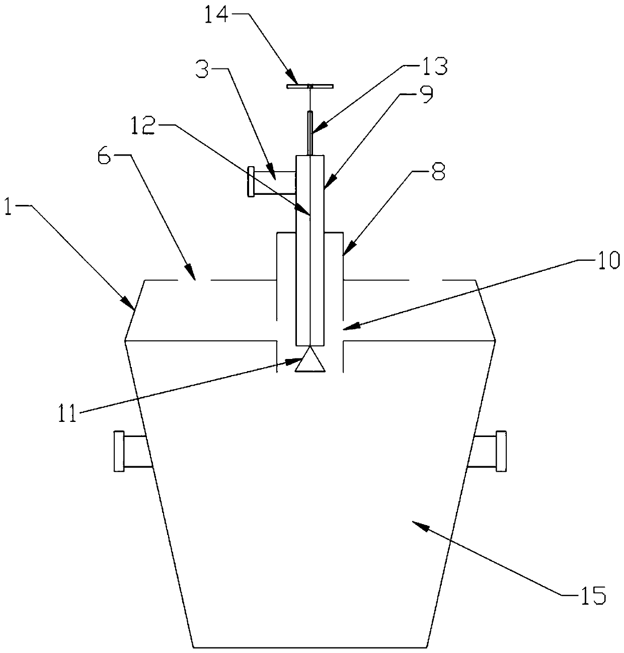
[0030] Such as Figure 1-Figure 2 As shown, the present invention includes a cover 1 and a burner 4 arranged on the cover 1. The cover 1 is hollow and has an air suction port 6 on the top; The air inlet 10 of the burner 4 is located inside the cover 1 and communicates with the air suction port 6 . A plurality of partitions 2 are arranged inside the cover 1 , and the partitions 2 form an air duct to connect the air suction port 6 with the air intake port 10 .

[0031] The burner 4 includes a combustion tube 8 and a nozzle 9 coaxial with the combustion tube 8 and inserted in the combustion tube 8; the nozzle 9 is provided with a gas pipeline interface 3; the air inlet 10 is arranged on the side wall of the combustion tube 8 . Preferably the air inlet...


PUM


Abstract

The invention discloses a steel ladle baking device which has an above structure. A rotary connector is omitted, a metal flexible pipe is adopted for connecting an external fuel gas pipeline so as toeliminate a potential safety hazard of gas leakage since the rotary connector is frequently damaged, meanwhile, a thermal insulation layer is added, a specially-designed nozzle is adopted, an originalcombustion fan, an induced draft fan and a heat accumulator are omitted, and the residual heat of a ladle cover is used for heating air. Since fuel gas owns certain pressure, the exhaust inlet of theladle cover generates negative pressure under a function of fuel gas pulling power, external air is automatically sucked into the interlayer channel of the ladle cover, and then, and the external airis preheated to be fully mixed and burnt with the fuel gas in the nozzle.

Description

technical field [0001] The invention relates to a device for toasting a ladle. Background technique [0002] The ladle generally needs to be roasted by a roaster after it is newly laid and before it is filled with molten steel. The ladle baker currently used in the steelmaking plant is a regenerative structure, and its burner is a casing type, which is composed of a hollow shaft, a combustion fan, an induced draft fan, a reversing valve, a heat storage body, a burner, and a cover; A gas chamber and a combustion-supporting air chamber are arranged inside the hollow rotating shaft, separated by a blind plate in the middle, one end is connected to the gas pipeline and the combustion-supporting air pipeline, and the other end is connected to the heat storage body. A pair of regenerators are switched by the reversing valve, the air is switched by the reversing valve, and after being preheated by the regenerator B, it reaches the burner for combustion. The reversing valve discha...

Claims


Application Information

Patent Timeline
IPC IPC(8): B22D41/01
CPCB22D41/01
Inventor 游思林冉顶立尹文廖勇胡友波高华斌
Owner SICHUAN DESHENG GRP VANADIUM & TITANIUM CO LTD
Why Eureka
Try Eureka