
Steel member turning-over and position changing device

A technology for displacement devices and steel components, applied in auxiliary devices, metal processing equipment, auxiliary welding equipment, etc., can solve the problems of limited use scenarios and few functions, and achieve the effect of improving stability

Active Publication Date: 2020-03-27
CHINA CONSTR STEEL STRUCTURE ENG CO LTD
View PDF21 Cites 12 Cited by
  • Summary
  • Abstract
  • Description
  • Claims
  • Application Information

AI Technical Summary

Problems solved by technology

[0004] The purpose of the present invention is to provide a steel component turning and displacement device, through the design of the left turning mechanism and the right turning mechanism, it solves the problem that the existing steel component turning and shifting device has limited use scenarios and less functions

Method used


Image

  • Steel member turning-over and position changing device
  • Steel member turning-over and position changing device
  • Steel member turning-over and position changing device

Examples


Embodiment Construction

[0023] The following will clearly and completely describe the technical solutions in the embodiments of the present invention with reference to the accompanying drawings in the embodiments of the present invention. Obviously, the described embodiments are only some, not all, embodiments of the present invention. Based on the embodiments of the present invention, all other embodiments obtained by persons of ordinary skill in the art without creative efforts fall within the protection scope of the present invention.

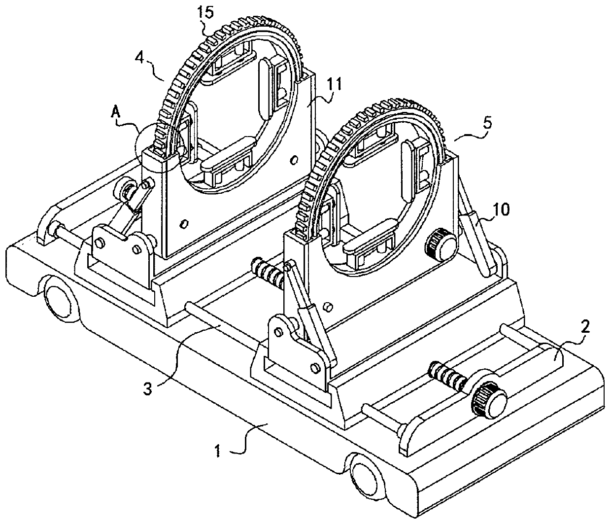
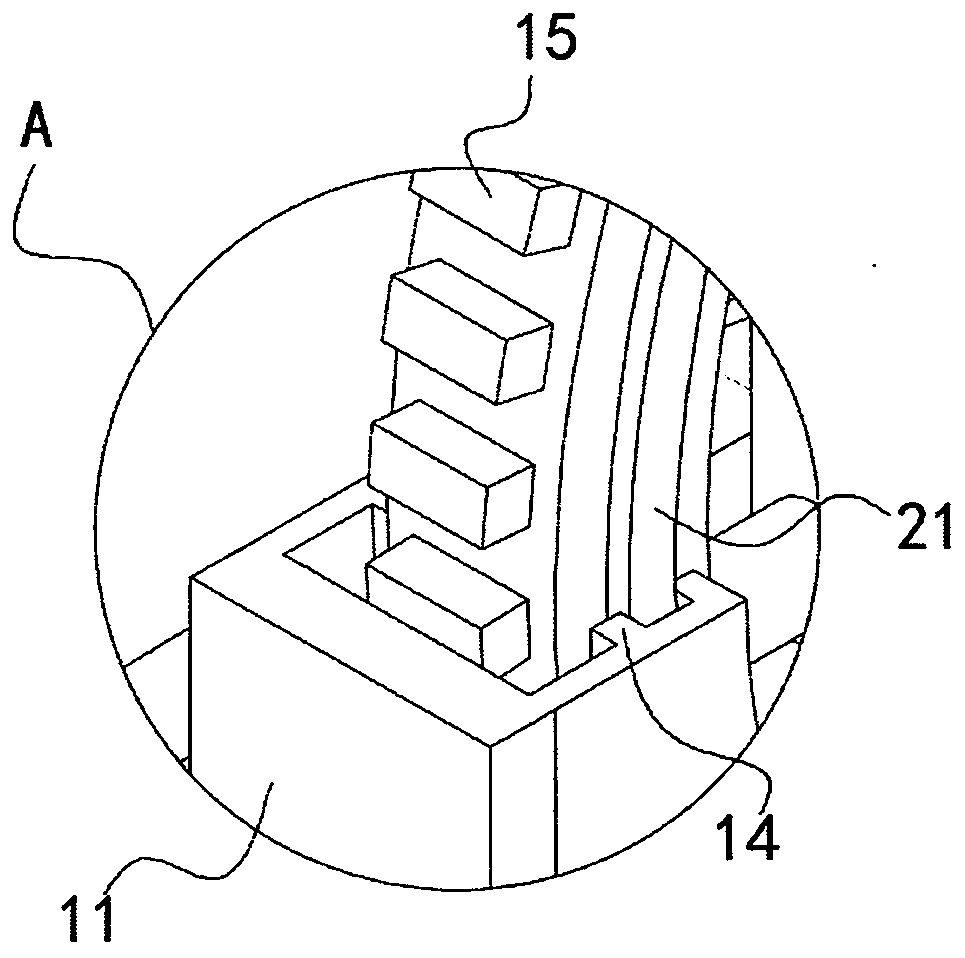
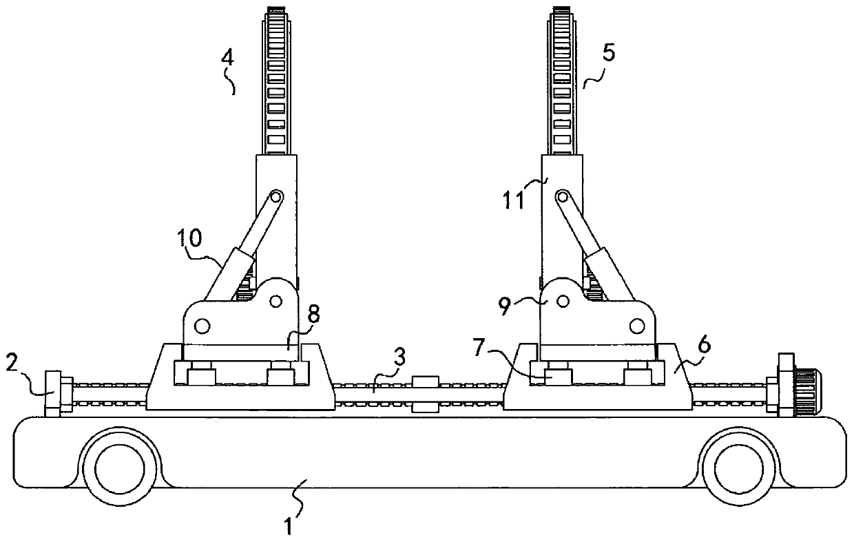
[0024] see Figure 1-4 , the present invention is a steel component turning and displacement device, comprising a self-driving trolley 1, a transmission mechanism, a steering structure and a remote central control structure are fixedly installed inside the self-driving trolley 1; the top surface of the self-driving trolley 1 is fixedly connected with two symmetrical arrangements The first support plate 2; the screw drive assembly 3 is fixedly installed between the ...


PUM


Abstract

The invention discloses a steel member turning-over and position changing device and relates to the technical field of auxiliary equipment for machining steel members. The steel member turning-over and position changing device comprises a self-driving trolley. Two first supporting plates arranged symmetrically are fixedly connected to the top face of the self-driving trolley. A screw rod transmission assembly is fixedly installed between the opposite surfaces of the two first supporting plates. A left turning-over mechanism and a right turning-over mechanism are connected to the periphery sideface of the screw rod transmission assembly. The left turning-over mechanism and the right turning-over mechanism each comprise a moving base. One surface of each moving base is connected with the screw rod transmission assembly. A hydraulic rod is fixedly connected to the top face of each moving base. A lifting base is fixedly connected to the top end of each hydraulic rod. Two second supportingplates are fixedly connected to the top faces of the lifting bases. According to the steel member turning-over and position changing device, by means of design of structures like a first electric pushing rod, the problem that a traditional turning-over and position changing device can only do plane type two-dimensional rotation, and cannot do three-dimensional space type rotation is solved, and by means of enlargement of the rotating range and the modularized combination structure, the use scene and the application range of the device can be effectively enlarged.

Description

technical field [0001] The invention belongs to the technical field of steel component processing auxiliary equipment, and in particular relates to a steel component turning and displacement device. Background technique [0002] The steel-concrete composite member is a new type of composite member proposed in Europe in the 1980s. The basic form of its section is to fill the steel member with concrete. This composite member has large bearing capacity, high rigidity and good fire resistance. Etc. [0003] During the welding process of steel members in the prior art, it is usually necessary to turn over and adjust the position of the weld seam to facilitate welding. The conventional adjustment method is to use a gantry crane to lift it and then manually turn it over. This is not only time-consuming and laborious, but also has low turning efficiency. It is dangerous; at the same time, the steel member can only be turned over at a fixed angle and cannot be turned over at any ang...

Claims


Application Information

Patent Timeline
Patent Type & Authority Applications(China)
IPC IPC(8): B23K37/047
CPCB23K37/047
Inventor 方春生于吉圣商晓福李大壮高如国
Owner CHINA CONSTR STEEL STRUCTURE ENG CO LTD
Learn More