Device for forming arc-shaped hanging groove in end surface of stone plate for building decoration
A technology for architectural decoration and stone slabs, which is applied in the field of devices for opening arc-shaped hanging grooves on the ends of stone slabs for architectural decoration, and can solve the problems of high cost, high labor intensity, and low efficiency
- Summary
- Abstract
- Description
- Claims
- Application Information
AI Technical Summary
Problems solved by technology
Method used
Image
Examples
Embodiment 1
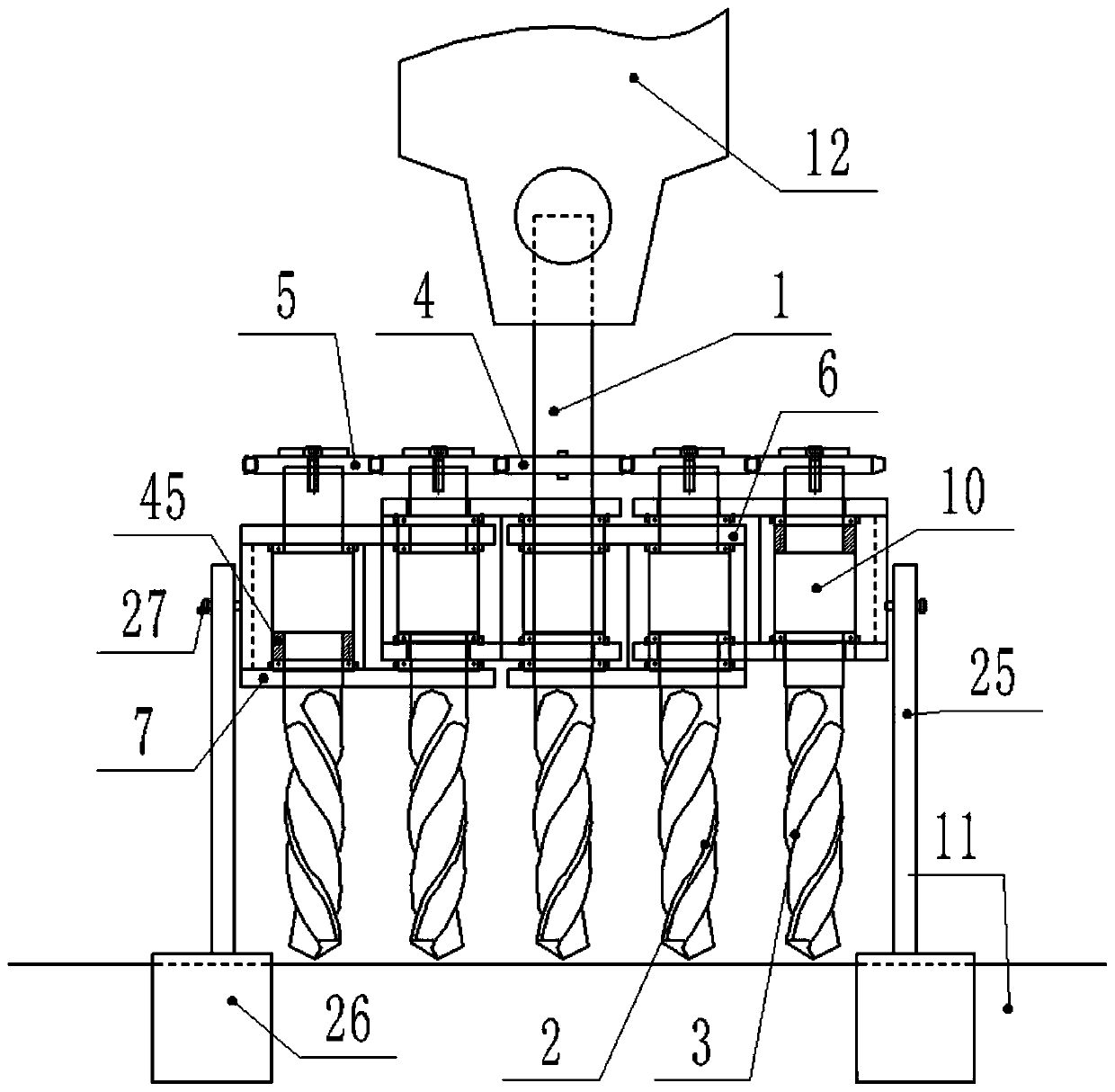
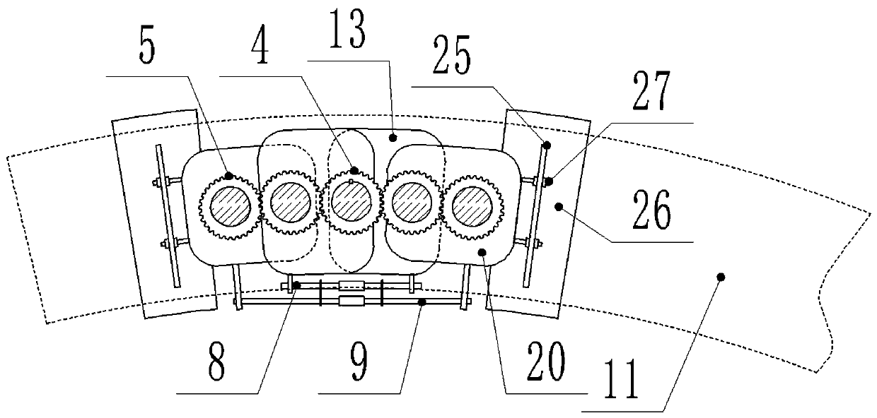
[0039] Such as Figure 1-10 As shown, the present invention is a device for opening arc-shaped hanging grooves on the end faces of stone slabs for architectural decoration. Ensure that the position of the dry hook is aligned, which leads to the limitation of excavation tools and equipment, and the material characteristics of the stone, which are fragile and not self-willed, which leads to the opening of 11 ends of the curved surface stone plate with this characteristic structure. The difficulty of arc-shaped grooves solves this industry problem. The present invention mainly includes the main drill bit 1, the first auxiliary drill bit 2, the second auxiliary drill bit 3, the transmission main gear 4, the transmission auxiliary gear 5, and the first drill bit connecting frame. 6. The second drill connecting frame 7, the first connecting frame arc adjustment device 8 and the second connecting frame arc adjusting device 9, the first auxiliary drill bit 2 and the second auxiliary d...
Embodiment 2
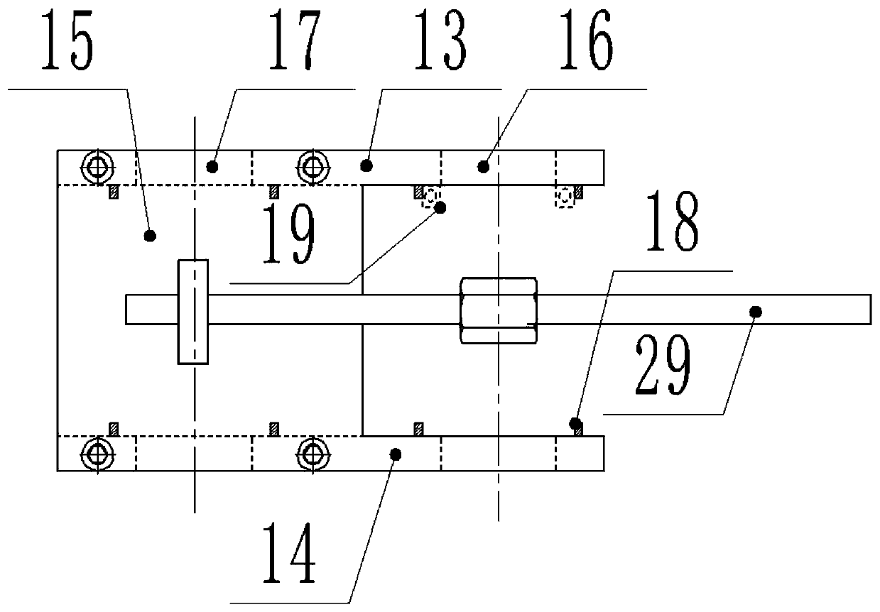
[0046] Such as Figure 1-10As shown, the present invention is a device for opening an arc-shaped hanging groove on the end surface of a stone plate for architectural decoration. Drill bit lower connecting plate 14 and the first drill bit upper and lower connecting plate 15, the first drill bit upper connecting plate 13, the first drill bit lower connecting plate 14 are all provided with main drill bit connecting hole 16 and the first auxiliary drill bit connecting hole 17, the main drill bit connects A pressure bearing installation sleeve 18 is provided on the corresponding inner side of the hole 16 and the first auxiliary drill bit connection hole 17, and a pressure bearing 19 is installed in the pressure bearing installation sleeve 18. The setting of the pressure bearing 19 can ensure the installation and connection accuracy, and at the same time will not Affecting the free rotation of the drill bit, the pressure bearing 19 is at first set on the drill bit, through the press...
Embodiment 3
[0050] Such as Figure 1-10 As shown, the present invention is a device for opening an arc-shaped hanging groove on the end surface of a stone plate for architectural decoration. On the basis of the above-mentioned embodiment, the outer end surface of the second drill bit connecting frame 7 is provided with a clamping frame mounting plate 24, The clamping frame mounting plate 24 is provided with a clamping frame, and the clamping frame includes a clamping vertical plate 25, a U-shaped bayonet 26 and a sliding column 27, and the U-shaped bayonet 26 is connected to the clamping vertical plate The lower end of 25 can be clamped on the arc-shaped stone plate 11 through the U-shaped bayonet 26, and two vertical parallel chutes are arranged on the clamping vertical plate 25, and sliding columns 27 are correspondingly installed in the chute. Said sliding column 27 is fixedly connected on the clamping frame mounting plate 24 again, and when using the electric drill 12 to carry out slo...
PUM
| Property | Measurement | Unit |
|---|---|---|
| diameter | aaaaa | aaaaa |
| thickness | aaaaa | aaaaa |
| thickness | aaaaa | aaaaa |
Abstract
Description
Claims
Application Information
 - R&D
- Intellectual Property
- Life Sciences
- Materials
- Tech Scout
- Unparalleled Data Quality
- Higher Quality Content
- 60% Fewer Hallucinations
Browse by: Latest US Patents, China's latest patents, Technical Efficacy Thesaurus, Application Domain, Technology Topic, Popular Technical Reports.
© 2025 PatSnap. All rights reserved.Legal|Privacy policy|Modern Slavery Act Transparency Statement|Sitemap|About US| Contact US: help@patsnap.com


