A connection structure and method for a powder conveying channel

A technology of conveying channel and connecting structure, which is applied in the field of powder conveying channel connecting structure and powder pneumatic conveying device, which can solve the problems of leakage, tearing and two-phase flow, etc., and achieve the effect of simple overall structure, efficient connection and avoiding wear

Active Publication Date: 2021-07-20
SHAANXI YANCHANG PETROLEUM GRP
View PDF5 Cites 0 Cited by
  • Summary
  • Abstract
  • Description
  • Claims
  • Application Information

AI Technical Summary

Problems solved by technology

[0005] For the above-mentioned similar working conditions, if a metal expansion joint is used to connect two sections with lined powder conveying channels, the inner wall of the metal expansion joint is easily washed and worn by the high-temperature powder entrained by the airflow. In addition, when the temperature of the metal expansion joint is high It is easy to be pulled apart and cause two-phase flow leakage

Method used


Image

  • A connection structure and method for a powder conveying channel

Examples


Embodiment Construction

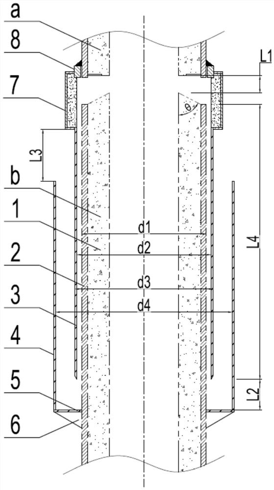
[0032] The present invention will be described in further detail below in conjunction with specific examples, but not as a limitation of the present invention.

[0033] Such as figure 1 As shown, the connection structure of the powder conveying channel of the present invention includes an inner cylinder 3 , an outer cylinder 4 , an outer cylinder bottom plate 5 , an outer cylinder rib plate 6 , an inner cylinder anti-wear block 7 and an inner cylinder receiving ring 8 . Both the upper section lining pipe a and the lower section lining pipe b used for connection are composed of two parts: the inner lining 1 of the delivery pipe and the outer shell 2 of the delivery pipe.

[0034] The inner cylinder 3, the inner cylinder anti-wear block 7 and the inner cylinder receiving ring 8 are sequentially combined in a seamless connection, and finally seamlessly connected with the conveying pipe shell 2 with the lining pipe a on the upper section, specifically the inner cylinder 3 After t...


PUM


Abstract

The invention discloses a connection structure and method for a powder conveying channel. The connection structure includes an inner cylinder, an outer cylinder, an inner cylinder anti-wear block, and an inner cylinder receiving ring. The inner and outer cylinders nested in each other are set to realize the connection of the two joints with lined pipes. A radial expansion gap is reserved between the inner and outer cylinders and the lined pipes, and an expansion joint is reserved between the ends of the two joints with lined pipes. , to avoid the problem that the lined pipe expands and expands and radially expands to cause the pipe to be damaged, and the inner cylinder is provided with an anti-wear block at the expansion joint between the ends of the two lined pipes to prevent the powder from being transported from the reserved expansion Seam erosion and wear; when the inner and outer cylinder casing structures are installed, an appropriate amount of powder to be conveyed is poured into the annulus formed by the outer cylinder and the lower section liner pipe, and the inner cylinder is inserted into the outer cylinder to seal the gap, avoiding powder The risk of body leakage from expansion gaps and expansion joints is eliminated, and the reliable and efficient connection of channels is realized.

Description

technical field [0001] The invention relates to the field of powder engineering, and relates to a powder pneumatic conveying device, in particular to a powder conveying channel connection structure and method. Background technique [0002] Thermal stress and wear problems widely exist in engineering fields such as mineral processing, metallurgy, thermal energy and power, chemical industry and oil refining. For the process of pneumatic conveying of high-temperature powder, the erosion of particles on the wall of the container is usually serious. In addition, there are temperature changes in the conveying channel from cold start to hot operation or the reverse process, which in turn causes thermal stress of thermal expansion and contraction Therefore, it is necessary to overcome thermal stress and wear problems at the same time when designing high-temperature powder conveying channels. [0003] In consideration of wear and heat insulation, wear-resistant refractory materials ...

Claims


Application Information

Patent Timeline
Patent Type & Authority Patents(China)
IPC IPC(8): B65G53/52B65G53/16B65G53/34
CPCB65G53/16B65G53/34B65G53/52B65G53/523
Inventor 黄勇王武生张月明杨会民刘巧霞王研靳皎郝婷王蒙
Owner SHAANXI YANCHANG PETROLEUM GRP
Why Eureka
Try Eureka