Cylinder body combined constant-liquid-level gas-liquid separator

A gas-liquid separator and combined technology, which is used in the production of fluids, wellbore/well components, and earth-moving drilling, etc., can solve the problems of hysteresis, small oil well holes, and high pressure, and reduce the impact height and strength. Number of air bubbles, weakening effect of axial shock

Inactive Publication Date: 2020-03-27
HARBIN ENG UNIV
View PDF6 Cites 0 Cited by
  • Summary
  • Abstract
  • Description
  • Claims
  • Application Information

AI Technical Summary

Problems solved by technology

[0005] 1. The gas-liquid separator is placed at a distance of 1,000 meters underground, and the space is so small that personnel cannot reach the installation position of the separator to perform manual liquid level control in real time;
[0006] 2. The hole of the oil well is narrow and only slightly larger than the diameter of the pipeline. It is very difficult to arrange the supporting measurement and control equipment. At the same time, when the equipment is damaged, the entire pipeline needs to be taken out, and the maintenance cost is high;
[0007] 3. The operating environment pressure of the separator is as high as several megapascals, and the measuring device that can operate normally in this high-pressure environment cannot meet the accuracy requirements of liquid level measurement;
[0008] 4. The liquid phase outlet flow is controlled by the ground cable, the control sensitivity is poor and has hysteresis, which cannot meet the requirements of precise real-time control

Method used


Image

  • Cylinder body combined constant-liquid-level gas-liquid separator
  • Cylinder body combined constant-liquid-level gas-liquid separator
  • Cylinder body combined constant-liquid-level gas-liquid separator

Examples


Embodiment approach 1

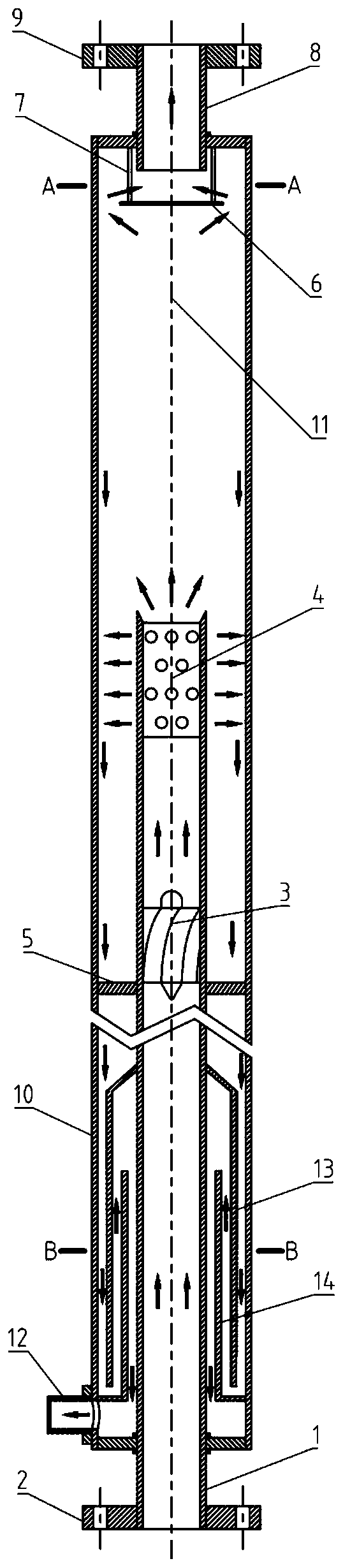
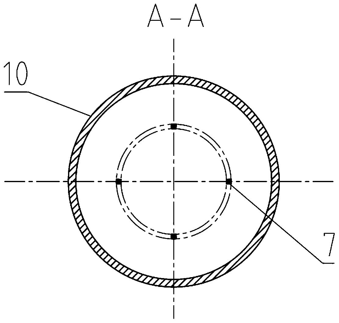
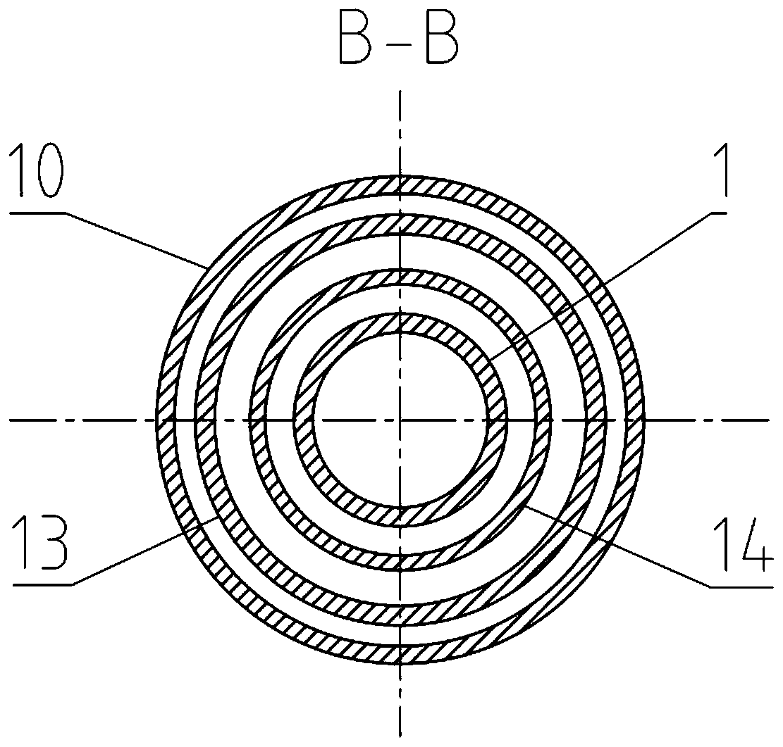
[0036] Embodiment 1: Combining Figure 1-3, a cylinder combined constant liquid level gas-liquid separator provided by the present invention, the main structure of the separator is composed of mutually nested cylinder structures, including a core cylinder 1, an outer cylinder 10, a drainage cylinder 13, and a liquid control cylinder 14 , and the upper end of the outer cylinder 10 is provided with a gas phase outlet 8, and the lower end is provided with a liquid phase outlet 12; a water barrier 6 is arranged below the gas phase outlet 8, and is fixed on the top of the outer cylinder 10 by a connecting rod 7; The upper part of 1 is provided with a drain section 4, and there are multiple rows of drain holes in the drain section 4; an impeller 3 is placed below the drain section 4 in the core tube 1; A drainage tube 13 and a hydraulic control tube 14 are arranged, the top of the drainage tube 13 is fixed on the outer wall of the core tube 1 , and the bottom of the hydraulic contro...

Embodiment approach 2

[0041] Embodiment 2: Combining Figure 4 , a cylinder combined gas-liquid separator provided by the present invention, comprising: a core cylinder 1, an inlet flange 2, a secondary impeller 23, a liquid discharge section 4, an anti-vibration strip 5, a water retaining plate 6, a connecting rod 7. Separator gas phase outlet 8, outlet flange 9, outer cylinder 10, water shielding ring 21, separator liquid phase outlet 12, drainage tube 13, liquid control tube 14, tertiary separation orifice plate 15, secondary separation Orifice plate 16, primary separation orifice plate 17, outlet cylinder 18, primary impeller 19. On the basis of Embodiment 1, an outlet cylinder 18 is added, and the impeller is changed into a primary impeller 19 and a secondary impeller 23. The primary impeller 19 is installed in the core cylinder 1, and the secondary impeller 23 is installed at the outlet of the core cylinder. The air outlet cylinder 18 is Permeable structure, the outlet tube 18 is located abo...


PUM


Abstract

The invention aims to provide a cylinder body combined constant-liquid-level gas-liquid separator, which comprises an outer cylinder, a drainage cylinder, a liquid control cylinder and a core cylinder. The top of the core cylinder extends into the position above the middle in the outer cylinder, the bottom of the core cylinder extends out of the bottom of the outer cylinder, the liquid control cylinder is arranged outside the core cylinder, the drainage cylinder is arranged outside the liquid control cylinder and located in the outer cylinder, the upper end of the drainage cylinder is connected with the outer wall of the core cylinder, the lower end of the liquid control cylinder is connected with the inner wall of the outer cylinder, the outer cylinder is provided with a separator liquidphase leading-out opening, the position of the separator liquid phase leading-out opening is located at the bottom end of the outer cylinder, an impeller is mounted in the core cylinder, a liquid drainage section is arranged on the upper part of the core cylinder, a separator gas phase leading-out opening is mounted in the top of the outer cylinder, a water baffle is arranged on the lower part ofthe separator gas phase leading-out opening and connected with the top of the outer cylinder through a connecting rod, an inlet flange is mounted at the bottom of the core cylinder, and an outlet flange is mounted at the top of the separator gas phase leading-out opening. Efficient separation can still be achieved without the mode that external intervention is conducted to adjust and control the liquid level.

Description

technical field [0001] The invention relates to a gas-liquid separation device, in particular to a downhole gas-liquid separation device. Background technique [0002] Gas-liquid separation technology has a wide range of applications in petrochemical, energy utilization, nuclear energy development and other fields. Downhole gas-liquid separation is of great significance for oil production and prolonging the economic life of high liquid-cut wells. The gas-liquid mixture to be separated downhole has the characteristics of wide range of gas-liquid flow rate and various flow patterns. [0003] At present, a variety of high-efficiency gas-liquid separators suitable for a wide range of gas-liquid flow rates and diverse flow patterns have been proposed (“a double-barrel gas-liquid separator”, CN 110075622 A; “a wide-flow multi-flow type high-efficiency gas-liquid separator”) liquid separator", CN 110075619A; "a combined high-efficiency gas-liquid separator", CN 110075618 A; "a re...

Claims


Application Information

Patent Timeline
Patent Type & Authority Applications(China)
IPC IPC(8): E21B43/38
CPCE21B43/38
Inventor 范广铭曾晓波祝福强阎昌琪侯明文赵伟光赵乐
Owner HARBIN ENG UNIV
Why Eureka
Try Eureka