Annular mist spray dust removal device

A dust removal device and ring-shaped technology, which is applied in safety devices, dust prevention, mining equipment, etc., can solve problems such as poor dust removal effect, and achieve the effects of protecting the health of employees, high promotion value, and good dust reduction effect

Inactive Publication Date: 2020-03-27
临沂矿业集团菏泽煤电有限公司
View PDF7 Cites 2 Cited by
  • Summary
  • Abstract
  • Description
  • Claims
  • Application Information

AI Technical Summary

Problems solved by technology

[0003] Aiming at the problem that the existing dust removal device has poor dust removal effect during the construction of the pressure relief hole, the present invention provides an annular spray dust removal device

Method used


Image

  • Annular mist spray dust removal device
  • Annular mist spray dust removal device
  • Annular mist spray dust removal device

Examples


Embodiment 1

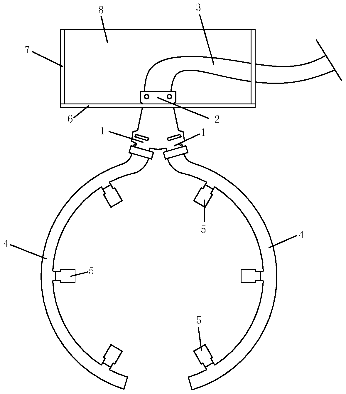
[0023] to combine Figure 1 to Figure 3 , an annular spray dedusting device, comprising an annular spray structure and a fixed frame structure.

[0024] The annular spray structure includes a three-way joint, and the three-way joint includes two oblique ports 1 .

[0025] Specifically, the three-way joint is inverted Y-shaped, the upper part of the three-way joint is the main interface 2, the main interface is connected to the water inlet pipe 3, the inclined interface 1 is arranged at the lower part of the three-way joint, and the two inclined interfaces are arranged opposite to each other.

[0026] The water inlet pipe is threaded with the main interface, and the arc pipe is threaded with the oblique interface. Of course, it can also be connected through other existing methods.

[0027] An arc-shaped tube 4 is connected to the oblique interface 1, and the arc-shaped mouths of the two arc-shaped tubes face each other, and a plurality of nozzles 5 are arranged on the inside ...

Embodiment 2

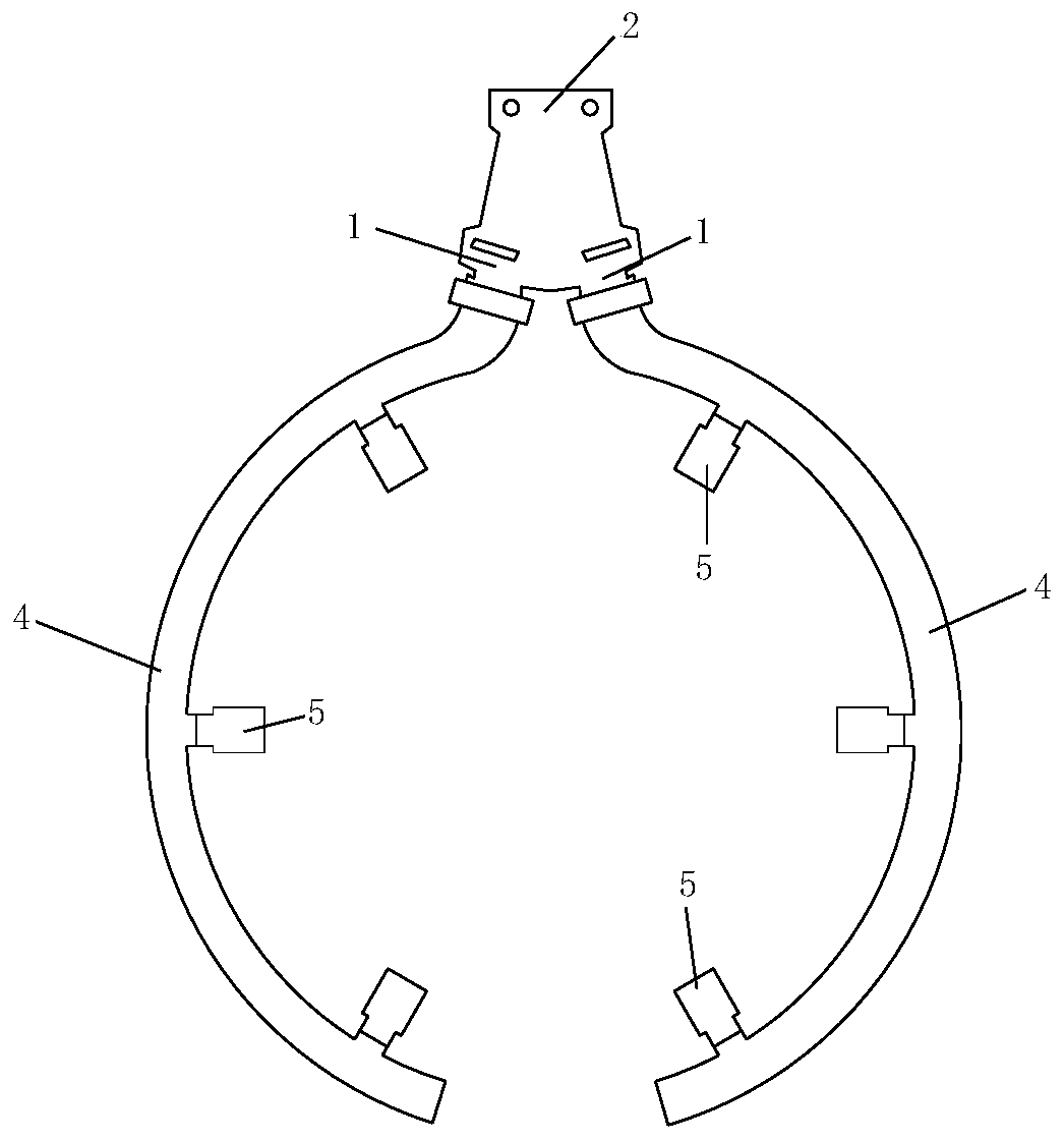
[0035] to combine figure 1 , figure 2 and Figure 4 , an annular spray dedusting device, comprising an annular spray structure and a fixed frame structure.

[0036] The annular spray structure includes a three-way joint, and the three-way joint includes two oblique ports 1 .

[0037] Specifically, the three-way joint is inverted Y-shaped, the upper part of the three-way joint is the main interface 2, the main interface is connected to the water inlet pipe 3, the inclined interface 1 is arranged at the lower part of the three-way joint, and the two inclined interfaces are arranged opposite to each other.

[0038] The water inlet pipe is threaded with the main interface, and the arc pipe is threaded with the oblique interface. Of course, it can also be connected through other existing methods.

[0039] An arc-shaped tube 4 is connected to the oblique interface 1, and the arc-shaped mouths of the two arc-shaped tubes face each other, and a plurality of nozzles 5 are arranged...


PUM


Abstract

The invention discloses an annular mist spray dust removal device. The annular mist spray dust removal device comprises an annular mist spray structure and a fixed frame structure, wherein the fixed frame structure fixes the annular mist spray structure on a coal wall, the annular mist spray structure comprises a three-way joint, the three-way joint comprises two inclined connection ports, the inclined connection ports are connected with arc-shaped pipes, the arc-shaped openings of the two arc-shaped pipes are opposite, and a plurality of spray heads are arranged on the inner sides of the arc-shaped pipes. When a drill bit of a hydraulic drill carriage is drilled, the fixed frame structure fixes the annular mist spray structure above a drill hole, the annular mist spray structure surroundsthe drill bit, the drill bit is located at the circle center position of the ring-like structure, when the drill bit performs drilling, the spray heads perform mist spray, the coal dust generated bydrilling is fully covered by the mist spray, the excellent dust falling effect is achieved, the annular mist spray dust removal device has remarkable effects of guaranteeing the health of workers andguaranteeing the ventilation quality of the mining working face, and the popularization value is high.

Description

technical field [0001] The invention relates to the field of dust removal in the construction process of pressure relief holes in coal mines, in particular to an annular spray dust removal device. Background technique [0002] With the increasing amount of anti-scouring and pressure relief works, a large amount of coal dust will be generated during the construction of large-diameter (150mm) pressure relief holes, which will seriously affect the air supply quality of the mining face. The existing dust removal devices are generally installed in the pressure relief holes A spray head is placed above for dust removal, but the dust removal effect of this solution is not good, and large coal dust will still be generated, so a new type of dust removal device needs to be involved. Contents of the invention [0003] Aiming at the problem that the existing dust removal device has poor dust removal effect during the construction of the pressure relief hole, the invention provides an ...

Claims


Application Information

Patent Timeline
Patent Type & Authority Applications(China)
IPC IPC(8): E21F5/04
CPCE21F5/04
Inventor 郑义宁张海超李存禄秦晓强高伟张晓然徐少勤毕艳芳周均民赵艳鹏
Owner 临沂矿业集团菏泽煤电有限公司
Why Eureka
Try Eureka