
Rotation blockage detection method and device

A detection method and detection device technology, applied in the direction of motor generator testing, etc., to achieve the effect of strong practicability, high safety and reliability

Active Publication Date: 2020-03-27
GUANGDONG WELLING ELECTRIC MACHINE MFG +1
View PDF14 Cites 3 Cited by
  • Summary
  • Abstract
  • Description
  • Claims
  • Application Information

AI Technical Summary

Problems solved by technology

For occasions where position sensorless control is used, especially the torque current control method, it is impossible to determine whether the cause of the current increase is a locked rotor or the position angle is too small, resulting in the failure to pass the sampling phase current or mutual induction phase current. method to determine whether a stall occurs

Method used


Image

  • Rotation blockage detection method and device
  • Rotation blockage detection method and device
  • Rotation blockage detection method and device

Examples


Embodiment Construction

[0036] In order to understand the above-mentioned purpose, features and advantages of the present invention more clearly, the present invention will be further described in detail below in conjunction with the accompanying drawings and specific embodiments. It should be noted that, in the case of no conflict, the embodiments of the present application and the features in the embodiments can be combined with each other.

[0037] In the following description, many specific details are set forth in order to fully understand the present invention. However, the present invention can also be implemented in other ways different from those described here. Therefore, the protection scope of the present invention is not limited by the specific details disclosed below. EXAMPLE LIMITATIONS.

[0038] Embodiments of the first aspect of the present invention provide a locked rotor detection method.

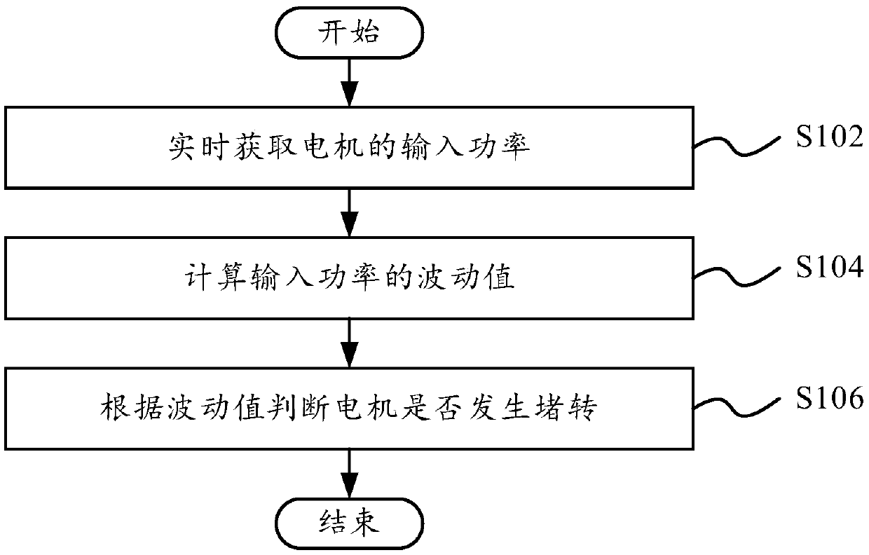
[0039] figure 1 A schematic flowchart of a stall detection method according to an embodime...


PUM


Abstract

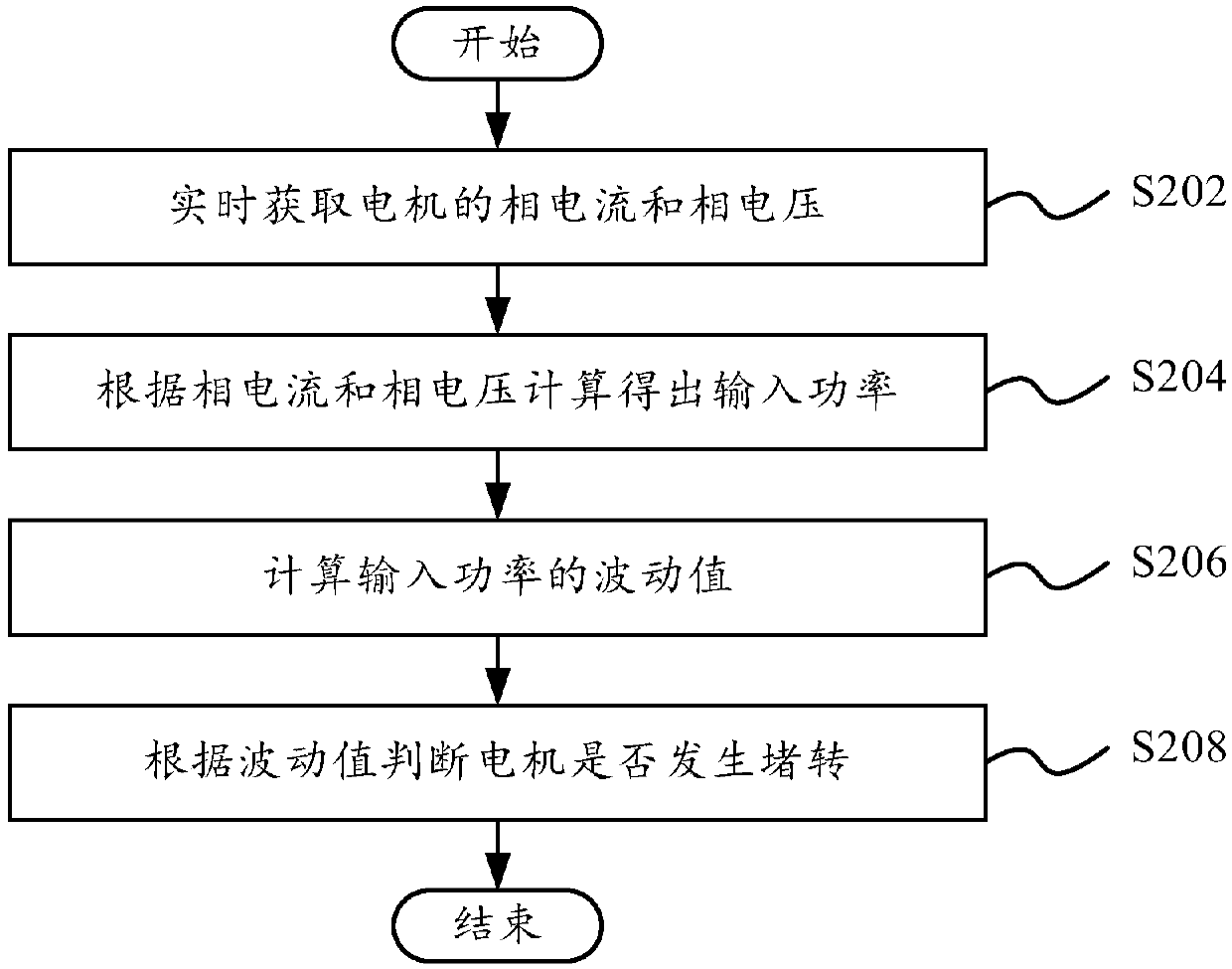
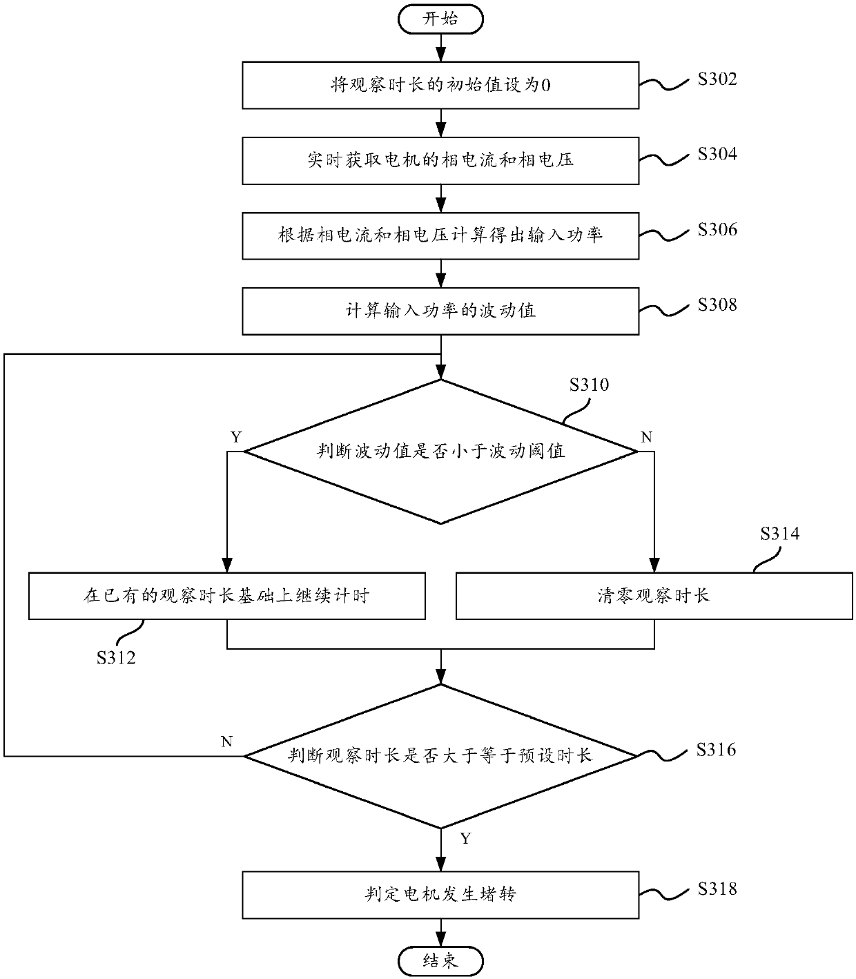
The invention provides a locked-rotor detection method and device, a computer readable storage medium and a motor driving device, and the locked-rotor detection method comprises the steps: obtaining the input power of a motor in real time; calculating a fluctuation value of an input power; and comparing the fluctuation value with the fluctuation threshold value, and when the fluctuation value is continuously smaller than the fluctuation threshold value within a preset duration, judging that the motor stalls. The invention provides a locked-rotor detection method. The invention is especially suitable for a sensorless AC motor. By monitoring the fluctuation value of the input power which is not influenced by the position angle, whether the motor is locked-rotor can be accurately detected, the scheme can be applied to a torque current control mode or a speed control mode of the motor, the defects in the prior art are overcome, the practicability is high, and the safety and reliability arehigh.

Description

technical field [0001] The present invention relates to the field of motor control, in particular to a locked-rotor detection method, a locked-rotor detection device, a computer-readable storage medium and a motor drive device. Background technique [0002] When the motor rotates at zero speed, it still outputs torque, that is, it stalls. There are many reasons for the motor to stall, including mechanical or man-made, such as: the contact between the rotor and the stator is stuck, the driven equipment is stuck, the equipment is too loaded and the motor cannot be driven, etc., all of which will cause the stall. [0003] For current AC motors, such as three-phase motors, the stall protection mainly judges the stall phenomenon of the motor by sampling the phase current or the magnitude of the mutual inductance phase current. When the current is very large, it is considered that a stall has occurred. However, the product of the current and the sine value of the position angle i...

Claims


Application Information

Patent Timeline
Patent Type & Authority Applications(China)
IPC IPC(8): G01R31/34
CPCG01R31/34
Inventor 程云峰
Owner GUANGDONG WELLING ELECTRIC MACHINE MFG
Learn More