Bus duct and bus duct joint thereof

A technology of busway and trapezoidal groove, which is applied in the direction of docking busbar, busbar installation, cooling busbar device, etc., which can solve the problems of easy temperature rise of connecting rod, heating of nut, need for regular tightening, etc., so that it is not easy to heat up and strengthen Heat dissipation, improve the effect of stability

Inactive Publication Date: 2020-03-27
HUBEI UNIV OF TECH
View PDF1 Cites 14 Cited by
  • Summary
  • Abstract
  • Description
  • Claims
  • Application Information

AI Technical Summary

Problems solved by technology

The heat dissipation structure of a busway joint in the above-mentioned patent has the following disadvantages: when the device generates heat, the temperature of the conne

Method used


Image

  • Bus duct and bus duct joint thereof
  • Bus duct and bus duct joint thereof
  • Bus duct and bus duct joint thereof

Examples


Embodiment 1

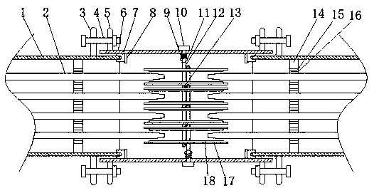
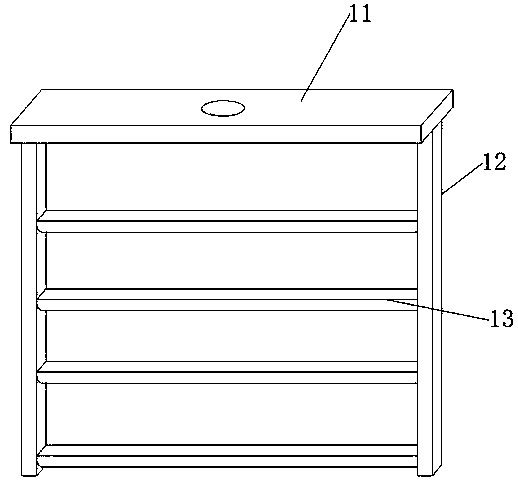
[0025] refer to Figure 1-3 , a bus duct and its bus duct connector, including two main bodies 1, the inside of the two main bodies 1 are provided with conductive bars 2, the top and bottom ends of one side of the conductive bar 2 are provided with inclined plane openings, the two main bodies 1 The outside of the protective cover 6 is provided with a circular through hole at the top and bottom of the protective cover 6, and the protective cover 6 is provided with fastening bolts 10 at the two circular through holes, and one end of the fastening bolt 10 is threaded A moving plate 11 is connected, and fixed rods 12 are welded on both sides of the moving plate 11. A moving rod 13 is welded between the two fixed rods 12. An insulating sheet 17 is arranged on the top of the moving rod 13, and the top of the insulating sheet 17 is bonded There is a conductive piece 18, when installing, twist the two fastening bolts 10, the fastening bolts 10 make the moving plate 11 move, the two mo...

Embodiment 2

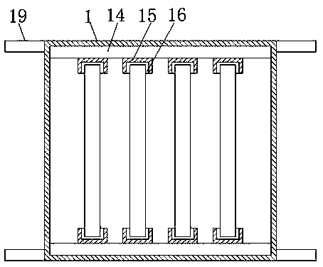
[0035] refer to Figure 4 , a bus duct and its bus duct connector. Compared with Embodiment 1, in this embodiment, in order to increase the waterproof performance of the device, the sealing ring 7 is provided with a water-swellable water stop 20 on one side of the trapezoidal groove, When water seeps into the inside of the trapezoidal groove of the sealing ring 7, the water-swelling waterstop 20 will swell when meeting water, so that the sealing performance of the device is improved.

[0036] During installation, twist the two fastening bolts 10, the fastening bolts 10 will move the moving plate 11, and the two moving plates 11 will move away from each other, and the spring 9 will be compressed to provide an axial force for the fastening bolts 10, preventing the moving plate 11 falls off easily, the two moving plates 11 drive the moving rod 13 on the fixed rod 12 to move, and the moving rod 13 drives the insulating sheet 17 to move until both sides of the conductive sheet 18 on ...


PUM


Abstract

The invention belongs to the technical field of cable installation, particularly relates to a bus duct and a bus duct joint thereof. Aiming at the problems that the resistance of a bus duct at a jointis large, heating is easy to occur, particularly, the temperature of the core-penetrating bolt is easily increased, and some core-penetrating bolts need to be fastened regularly, the following schemeis provided: the bus duct comprises two main bodies, conducting bars are arranged in the two main bodies, inclined surface openings are formed in the top ends and the bottom ends of one sides of theconducting bars, protective sleeves are arranged outside the two main bodies, and circular through holes are formed in the top ends and the bottom ends of the protective sleeves. According to the invention, the moving plate is moved through the fastening bolts, so that an insulating sheet moves until the two sides of each conducting strip make contact with the conducting bar, the fastening bolts continue to be twisted, the conducting strips begin to be bent and are tightly attached to the openings of the slopes of the conducting bars, the contact area is increased, every two adjacent conducting strips clamp the conducting bar, the fastening bolts are located on the two sides of the protective sleeve, the fastening bolts are not prone to temperature rise, and the stability of the fasteningbolts is improved.

Description

technical field [0001] The invention relates to the technical field of cable installation, in particular to a bus duct and a bus duct joint. Background technique [0002] Busway is a new circuit connection method, which can provide greater power for the distributed system, but the resistance of the busway at the connection is relatively large, which is easy to generate heat and cause harm, especially the temperature of the core bolts is easy to increase, and some wear Core bolts also require regular tightening. [0003] After searching, the Chinese patent application number is CN201720135572.X, which discloses a heat dissipation structure for busway joints, including a connecting plate group, which includes a plurality of connecting plates arranged in parallel, and two adjacent connecting plates Insulation plates are arranged between them; a heat dissipation plate is respectively arranged on both sides of the connection plate group, and a number of heat dissipation protrusi...

Claims


Application Information

Patent Timeline
IPC IPC(8): H02G5/00H02G5/06H02G5/10H01R9/00
CPCH01R9/00H02G5/007H02G5/06H02G5/10
Inventor 汪繁荣周子槊彭禄向堃
Owner HUBEI UNIV OF TECH
Why Eureka
Try Eureka