
Voltage conversion circuit, power system

A technology of voltage conversion circuit and conversion module, which is applied to battery circuit devices, circuit devices, battery load switching, etc., and can solve problems such as high cost of power supply systems, damage to load capacitors, and increased complexity of electrical components.

Active Publication Date: 2021-07-09
HUAWEI DIGITAL POWER TECH CO LTD
View PDF4 Cites 0 Cited by
  • Summary
  • Abstract
  • Description
  • Claims
  • Application Information

AI Technical Summary

Problems solved by technology

In the power supply system that provides the driving source in the electric vehicle / electric vehicle, when the high-voltage battery provides the high-voltage driving voltage for the load, because the high-voltage driving voltage is relatively high, if it is directly provided to the load capacitance and the working circuit in the load, due to the initial load capacitance When the power is turned on, the voltage and current are both zero, so if the high-voltage driving voltage is directly loaded on the load capacitor, it is easy to cause the load capacitor to be damaged due to the sudden increase of the current in a short period of time
[0003] At present, a pre-charging circuit is usually set between the high-voltage battery and the load capacitor, but the pre-charging circuit must at least include a relay and a high-power line current resistor. The existence of the pre-charging circuit not only leads to the complexity of the electrical components in the power system The height and volume increase, and because there are more components in the pre-charging circuit, the overall cost of the power system is higher

Method used


Image

  • Voltage conversion circuit, power system
  • Voltage conversion circuit, power system
  • Voltage conversion circuit, power system

Examples


Embodiment Construction

[0030] The technical solutions in the embodiments of the present application will be clearly and completely described below in conjunction with the drawings in the embodiments of the present application.

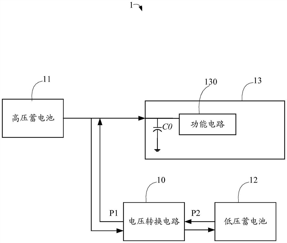
[0031] see figure 1 , which is a functional block diagram of the power supply system 1 in an embodiment of the present application. Such as figure 1 As shown, the power supply system 1 can be applied to driving devices such as automobiles and electric vehicles, and the power supply system 1 includes a voltage conversion circuit 10 , a high-voltage battery 11 , a low-voltage battery 12 and a load 13 .

[0032] The high-voltage battery 11 is electrically connected to the load 13 and electrically connected to the voltage conversion circuit 10 through the first port P1. The high-voltage battery 11 is used to provide the first DC voltage V1 for driving the load capacitor C0 in the load 13 and the functional circuit 130. . In this embodiment, the functional circuit 130 may be a...


PUM


Abstract

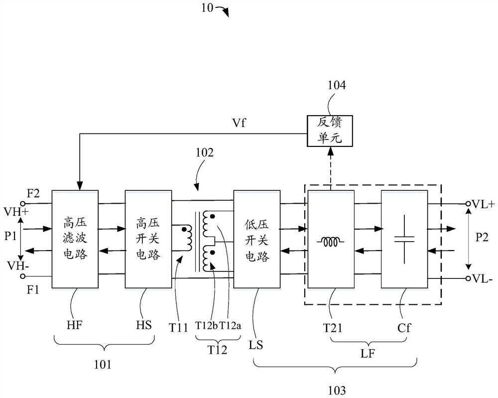
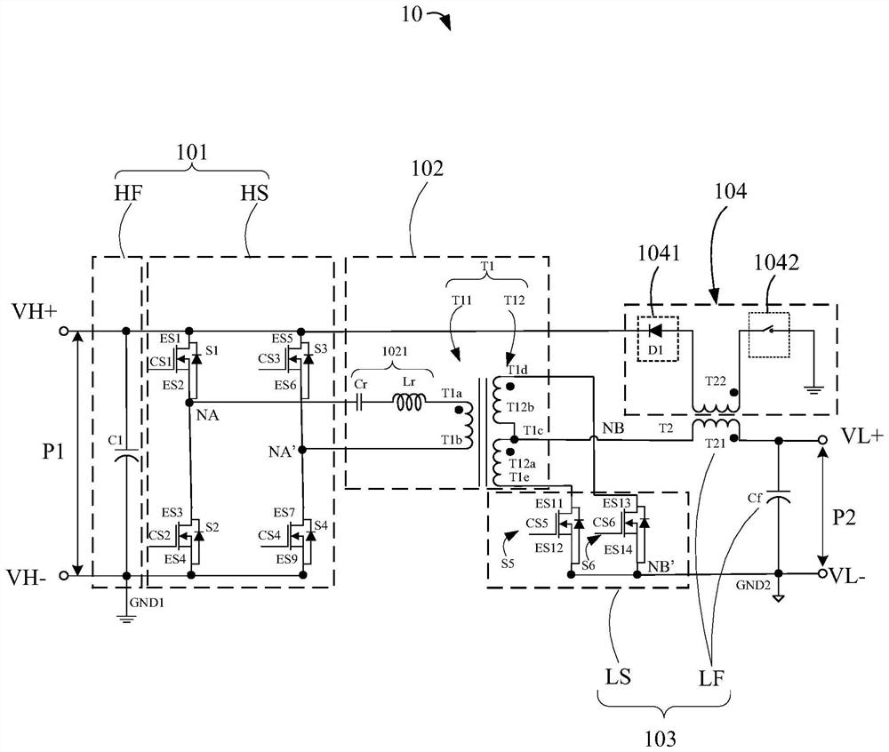
An embodiment of the present application provides a voltage conversion circuit with high charging efficiency and low cost, and provides a power supply system including the voltage conversion circuit, the power system is low in cost, small in size and complex lower. The voltage conversion circuit includes a high voltage conversion module, a transformer isolator, a low voltage conversion module and a feedback module. The high-voltage conversion module converts the first DC voltage received from the first port into a second DC voltage along the first direction through the transformer isolator and the low-voltage conversion module. The low-voltage conversion module receives the second DC voltage from the second port, and converts it into the first DC voltage along the second direction through the transformer isolator and the high-voltage conversion module. The feedback module is used to induce the electric energy generated when the low-voltage conversion module converts the second DC voltage along the second direction through electromagnetic induction, and transfer the induced electric energy to the high-voltage conversion module.

Description

technical field [0001] The present application relates to the technical field of DC voltage conversion, in particular to the technical field of bidirectional DC voltage conversion circuit and power supply system. Background technique [0002] With the development of technology in the field of new energy, the application of new energy vehicles is becoming more and more popular, for example, electric vehicles / electric vehicles (Electric Vehicle). In the power supply system that provides the driving source in the electric vehicle / electric vehicle, when the high-voltage battery provides the high-voltage driving voltage for the load, because the high-voltage driving voltage is relatively high, if it is directly provided to the load capacitance and the working circuit in the load, due to the initial load capacitance When the power is turned on, the voltage and current are both zero, so if the high-voltage driving voltage is directly loaded on the load capacitor, it is easy to caus...

Claims


Application Information

Patent Timeline
Patent Type & Authority Patents(China)
IPC IPC(8): H02M3/335H02J7/00
CPCH02M3/3353H02J7/0068H02M3/33584H02M3/33573H02M3/01H02M1/36H02M3/33507
Inventor 梁涛刘卫平梁永涛
Owner HUAWEI DIGITAL POWER TECH CO LTD
Learn More