
A pre-charge control device and method

A control device and pre-charging technology, applied in the direction of circuit devices, battery circuit devices, collectors, etc., can solve the problems of slow pre-charging speed, slow rising speed, low pre-charging efficiency, etc., and achieve the effect of increasing speed and improving efficiency

Active Publication Date: 2022-03-29
HANGZHOU HIKROBOT TECH CO LTD
View PDF17 Cites 0 Cited by
  • Summary
  • Abstract
  • Description
  • Claims
  • Application Information

AI Technical Summary

Problems solved by technology

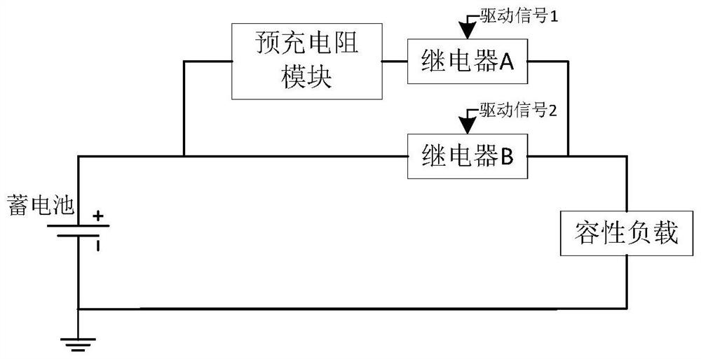
[0004] The above scheme adopts the method of sufficient delay, which will cause misjudgment of the damage of the pre-charging resistor module, and cannot guarantee that the pre-charging process can actually be completed. Furthermore, the speed of pre-charging depends entirely on the pre-charging branch. The hardware circuit has poor flexibility for different application situations
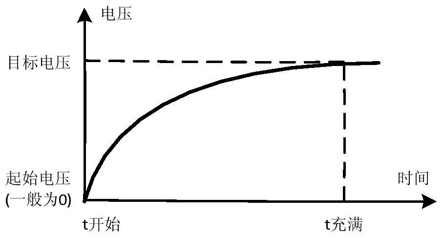
Most importantly, if figure 2 As shown in the above solution, as the pre-charging progresses, the rising speed of the voltage becomes slower and slower, resulting in a slower and slower pre-charging speed, which makes the pre-charging efficiency low.

Method used


Image

  • A pre-charge control device and method
  • A pre-charge control device and method
  • A pre-charge control device and method

Examples


Embodiment Construction

[0053] In order to make the purpose, technical solution and advantages of the present invention more clear, the present invention will be further described in detail below with reference to the accompanying drawings and examples.

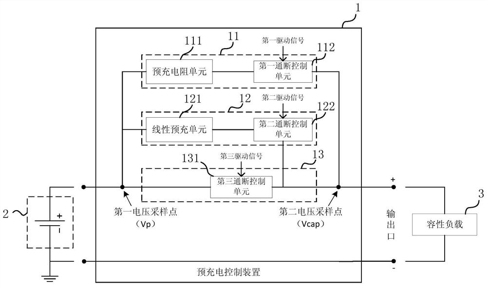
[0054] Such as image 3As shown, the precharge control device 1 of the present invention is arranged between the storage battery 2 and the capacitive load 3 . Wherein, the precharge control device 1 includes a resistance precharge branch 11, a linear precharge branch 12, a power supply branch 13 and a voltage sampling control module (not shown in the figure), the resistance precharge branch 11, the linear precharge branch The circuit 12 and the power supply branch circuit 13 are connected in parallel between the storage battery 2 and the capacitive load 3 . Among them, the resistance pre-charging branch 11 is turned on or off under the driving of the first driving signal, the linear pre-charging branch 12 is turned on or off under the driving of th...


PUM


Abstract

The invention discloses a precharge control device and method. The pre-charging control device includes a resistance pre-charging branch, a linear pre-charging branch and a power supply branch connected in parallel between the battery and the capacitive load; the voltage sampling control module collects the voltage of the battery terminal and the voltage of the capacitive load terminal respectively, and according to the collected The change of the voltage to control the first driving signal, the second driving signal and the third driving signal respectively; the resistance pre-charging branch is turned on or off under the drive of the first driving signal; the linear pre-charging branch is turned on or off under the driving of the second driving signal The power supply branch is turned on or off under the driving of the third driving signal. The pre-charging control device and method of the present invention increase the speed of the pre-charging process and improve the efficiency of the pre-charging.

Description

technical field [0001] The invention relates to the technical field of power supply control, in particular to a pre-charging control device and method. Background technique [0002] Currently, battery-powered mobile devices such as intelligent mobile robots and electric vehicles have been widely used. These devices mostly use higher-voltage batteries to supply power to the load, and when the battery supplies power, an instantaneous large charging current will be generated for the load of the device. For example, for an intelligent mobile robot, it uses a 48V battery to power the entire circuit, and there is a capacitive load with a large capacity. When the battery is powered, a large charging current is generated, which is likely to cause damage to system-related components. In order to solve this problem, a pre-charging control technical solution is proposed in the related art. [0003] Such as figure 1 As shown, the dual-relay resistance scheme can be adopted, in which ...

Claims


Application Information

Patent Timeline
Patent Type & Authority Patents(China)
IPC IPC(8): H02J7/00
Inventor 周磊杰徐慧鑫谢朝进魏彬
Owner HANGZHOU HIKROBOT TECH CO LTD
Learn More