
Heat dissipation protection device of electromechanical equipment

A technology for protection devices and electromechanical equipment, applied in electrical equipment structural parts, electrical equipment housings/cabinets/drawers, electrical components, etc., can solve the problems of high dust volume, easy damage of electronic components, easy accumulation inside the control cabinet, etc. , to achieve the effect of improving the heat dissipation effect

Active Publication Date: 2020-03-27
常山县常云包装材料有限公司
View PDF4 Cites 1 Cited by
  • Summary
  • Abstract
  • Description
  • Claims
  • Application Information

AI Technical Summary

Problems solved by technology

[0005] Aiming at the deficiencies of the prior art, the present invention provides a heat dissipation protection device for electromechanical equipment, which solves the problem that during the use of existing electromechanical equipment, especially some larger electromechanical equipment, a control cabinet will be configured to control the electromechanical equipment. , During the use of the control cabinet, a relatively high temperature will be generated. The traditional control cabinet relies on its own materials and cooling holes for heat dissipation. damage, and when the outside air is exchanged with the air inside the control cabinet, when the control cabinet is located outside, the amount of dust contained in the air is high, which will easily cause negative ions such as dust to be absorbed on the surface of the electronic components inside the control cabinet, affecting the use of the problem

Method used


Image

  • Heat dissipation protection device of electromechanical equipment
  • Heat dissipation protection device of electromechanical equipment
  • Heat dissipation protection device of electromechanical equipment

Examples


Embodiment

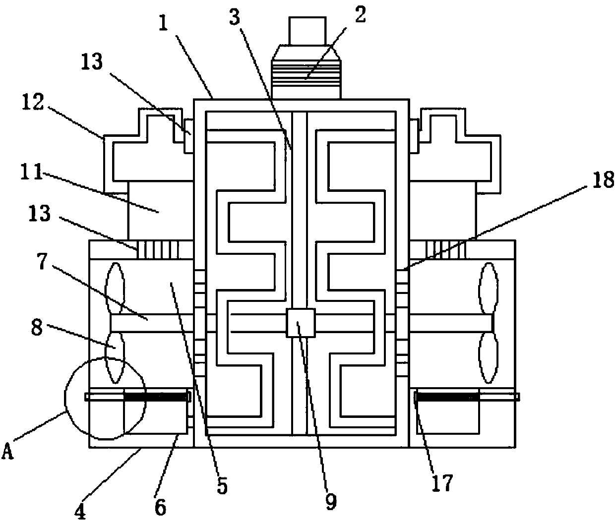
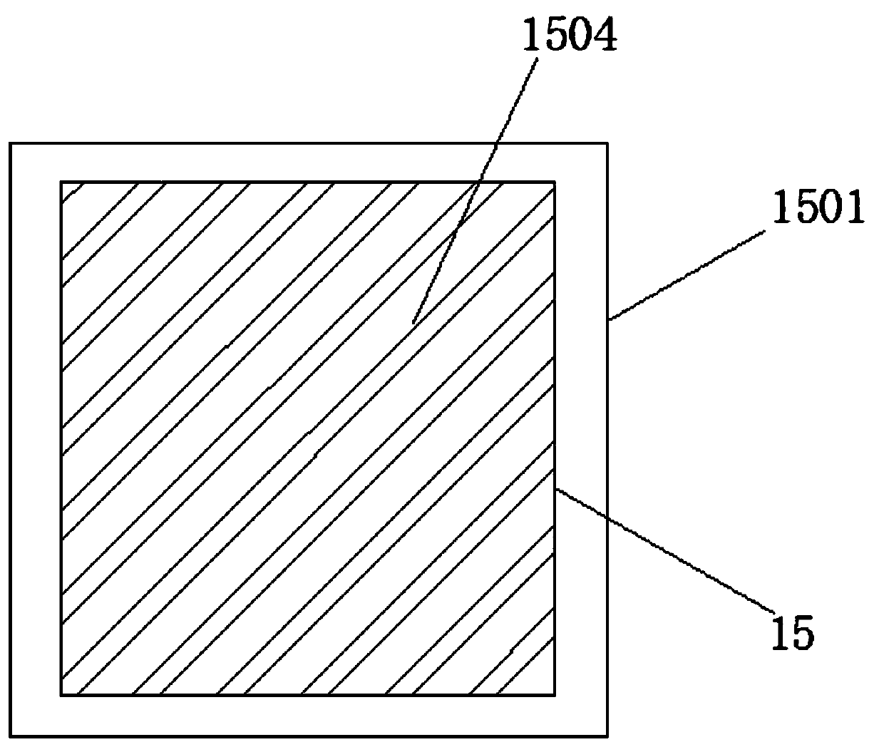
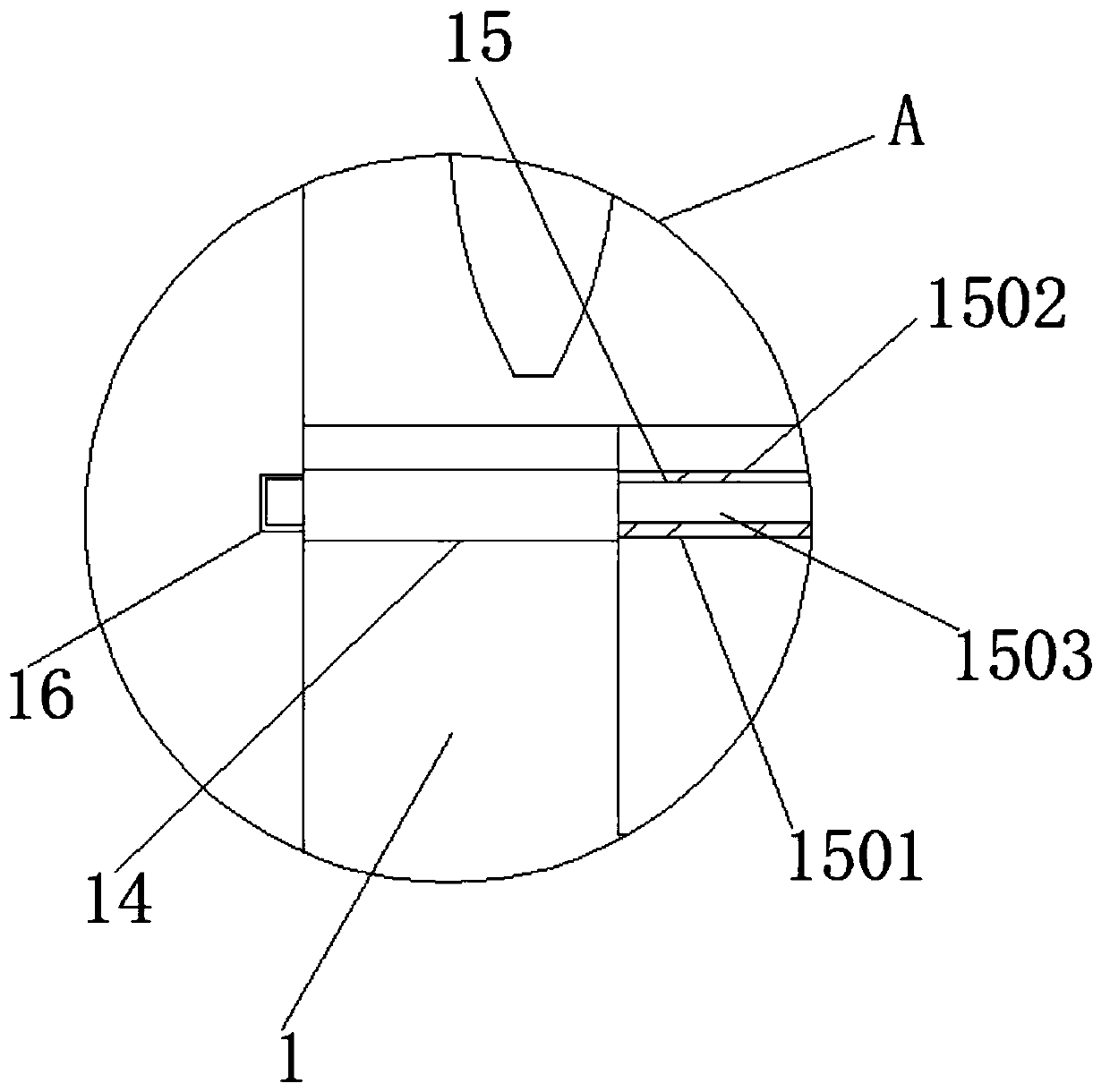
[0025] Example: refer to Figure 1-5 , a heat dissipation protection device for electromechanical equipment, including a cabinet body 1, a heat dissipation mechanism is provided on both sides of the cabinet body 1, a circulation mechanism is provided inside the cabinet body 1, and the top side wall of the cabinet body 1 A driving motor 2 is fixed, and the output shaft of the driving motor 2 is fixed with a rotating shaft 3 through a coupling. The end of the rotating shaft 3 away from the driving motor 2 extends to the bottom side wall of the cabinet body 1 for rotational connection. The two sides of the cabinet body 1 The walls are provided with a plurality of cooling holes 18 .

[0026] The heat dissipation mechanism includes a heat dissipation platform 4 fixed on the side walls of both sides of the cabinet body 1. The heat dissipation platform 4 is provided with a first through hole 5 penetrating left and right. The first through hole 5 communicates with the heat dissipation...


PUM


Abstract

The invention discloses a heat dissipation protection device of electromechanical equipment. The device comprises a cabinet body, heat dissipation mechanisms are arranged on the two sides of the cabinet body, a circulating mechanism is arranged in the cabinet body, a driving motor is fixed to the top end side wall of the cabinet body, a rotating shaft is fixed to an output shaft of the driving motor through a coupler, the end, away from the driving motor, of the rotating shaft extends to the bottom end side wall of the cabinet body to be rotationally connected, and multiple heat dissipation holes are formed in the two side walls of the cabinet body. According to the invention, rapid heat dissipation processing can be carried out on the control cabinet of the electromechanical equipment; exchange of external air and air in the cabinet body is accelerated, dust removal and water spraying cooling treatment can be carried out on the external air while exchange is carried out, the heat dissipation effect is further improved, and the heat dissipation effect is further improved through circulation of the circulating pipe and the cooling liquid in the cabinet body.

Description

technical field [0001] The invention relates to the technical field of electromechanical equipment, in particular to a heat dissipation protection device for electromechanical equipment. Background technique [0002] Electromechanical equipment generally refers to machinery, electrical appliances, and electrical automation equipment. In construction, it refers to the general term for machinery and pipeline equipment other than geotechnical, carpentry, steel bars, and muddy water. It is different from hardware and mostly refers to finished products that can achieve certain functions. [0003] During the use of existing electromechanical equipment, especially some larger electromechanical equipment, a control cabinet will be configured to control the electromechanical equipment. During the use of the control cabinet, a higher temperature will be generated. The traditional control cabinet relies on its own materials. And heat dissipation holes for heat dissipation, the heat di...

Claims


Application Information

Patent Timeline
Patent Type & Authority Applications(China)
IPC IPC(8): H05K5/02H05K7/20
CPCH05K5/0213H05K7/20136H05K7/20172H05K7/20218H05K7/20272
Inventor 萧飞
Owner 常山县常云包装材料有限公司
Learn More