Dust removal device for floor mat production

A technology of dust removal device and floor mat, which is applied in the direction of dust removal, application, household appliances, etc., and can solve the problems of poor dust removal effect of scraper floor mat and no cleaning brushes, etc.

Inactive Publication Date: 2020-03-31
安吉业晟家居用品有限公司
View PDF1 Cites 1 Cited by
  • Summary
  • Abstract
  • Description
  • Claims
  • Application Information

AI Technical Summary

Problems solved by technology

But this device is not equipped with cleaning brushes, and the dust removal ...

Method used


Image

  • Dust removal device for floor mat production
  • Dust removal device for floor mat production
  • Dust removal device for floor mat production

Examples


Embodiment 1

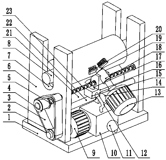
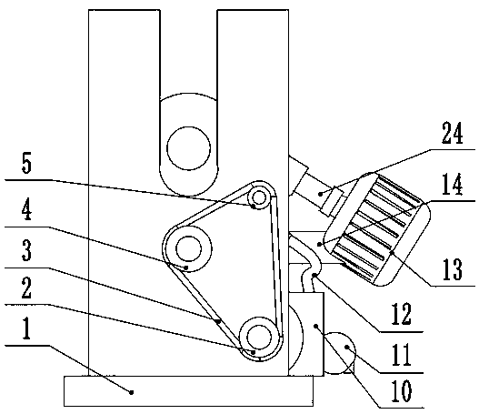
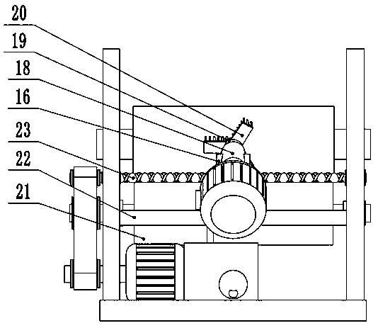
[0023] see Figure 1-3 , a dust removal device for floor mat production, comprising a bottom plate 1, side plates 6 are provided on the front and rear sides of the bottom plate 1, a placement groove 7 is arranged on the top of the side board 6, and a winding roller 8 is arranged inside the placement groove 7, and the side The bottom of the plate 6 is connected to the front and rear sides of the drive roller 21 in rotation. The right side of the bottom plate 1 is provided with a first drive motor 9. The output shaft of the first drive motor 9 is fixedly connected to the drive pulley 2, and the drive pulley 2 is connected by a belt 3. The first driven pulley 4, the first driven pulley 4 is fixedly connected to the front end of the driving roller 21, the right side of the side plate 6 is rotated to connect the front and rear sides of the screw mandrel 23, and the driving pulley 2 passes through the belt 3 Connect the second driven pulley 5, the second driven pulley 5 is fixedly c...

Embodiment 2

[0025] see image 3 , the other content of this embodiment is the same as that of Embodiment 1, the difference is that: the middle part of the upper surface of the bottom plate 1 is provided with a dust removal box 10, the top of the dust removal box 10 is connected to the bottom of the dust removal suction nozzle 17 through the air pipe 12, and the dust removal box The right side of 10 is provided with air pump 11. In order to prevent the dust sucked out by the dust removal nozzle 17 from leaking into the environment and affecting the working environment of the operator, a dust removal box 10 is arranged at the bottom of the bottom plate 1, and the dust extracted by the suction nozzle is filtered through the dust removal box 10, and when the device works for a period of time , it only needs to clean the dust removal box 10, which reduces the maintenance difficulty of the whole device.

[0026] In the implementation process of the present invention, start the first drive moto...


PUM


Abstract

The invention relates to the technical field of floor mat production, and discloses a dust removal device for floor mat production. The dust removal device comprises a bottom plate, wherein the frontand rear sides of the bottom plate are provided with side plates, the upper part of each side plate is provided with a placement groove, a winding roller is arranged in the placement grooves, the lower parts of the side plates are rotationally connected with the front side and the rear side of a driving roller, the right sides of the side plates are rotationally connected with the front side and the rear side of a lead screw, the middle part of the lead screw is provided with a sliding block, the lower part of the right side of the sliding block is provided with a motor fixing seat, the middlepart of the motor fixing seat is provided with a second driving motor, an output shaft of the second driving motor is fixedly connected with a rotating shaft, the end part of the rotating shaft is provided with brushes, the front surface of the sliding block is provided with a suction nozzle fixing seat, and the middle part of the suction nozzle fixing seat is provided with a dust removal suctionnozzle. According to the dust removal device for floor mat production, the rotating brushes are arranged on the lower part of the winding roller, so that the dust is separated from a floor mat through a physical method, and the suction nozzle is arranged beside the brushes, so that the flying dust is removed in time.

Description

technical field [0001] The invention relates to the technical field of floor mat production, in particular to a dust removal device for floor mat production. Background technique [0002] The PVC composite floor mat made of PVC paste resin as the main raw material needs a set of PVC calendered floor mat production system with calendering equipment as the core. Because the surface temperature of the floor mat is high after it comes out of the molding device, it needs to be installed on the frame of the floor mat production system. Fans are set up on the ground to cool down. During the cooling process, the two sides of the floor mat are prone to dust. The current PVC calendered floor mat production system has no treatment plan for this dust, and lacks a dust removal device. After the mat is rolled, it will be difficult to clean, which will eventually reduce the quality of the floor mat. [0003] Chinese patent (notification number: CN209237574U) discloses a dust removal devic...

Claims


Application Information

Patent Timeline
IPC IPC(8): B08B1/02B08B15/04B29C43/32B29L7/00
CPCB08B1/002B08B1/02B08B15/04B29C43/32B29L2007/002
Inventor 叶忠
Owner 安吉业晟家居用品有限公司
Why Eureka
Try Eureka